
Automatic grinding and drilling machine

A fully automatic, drilling rig technology, used in grinding machines, machine tools suitable for grinding workpiece edges, grinding/polishing equipment, etc. The effect of improving geometric flatness, improving work efficiency and reducing vibration amplitude

Inactive Publication Date: 2003-05-14
陈伟明
View PDF0 Cites 15 Cited by
  • Summary
  • Abstract
  • Description
  • Claims
  • Application Information

AI Technical Summary

Problems solved by technology

In the past, this kind of grinding and forming used a worm gear indexing mechanism to control the rotation angle of the sticking rod fixture, and ground the ball blank with the circumferential surface of the grinding and polishing disc to achieve grinding on each surface. The typical process includes : Loading → Grinding and polishing one side → Transfer → Grinding and polishing the other side and the top surface → Unloading. The disadvantages are: 1) Because the sticking rod fixture is longer, and the limit fulcrum at the middle worm wheel / worm is only One-way limit, large degree of freedom of elastic vibration, and the long-term high-frequency vibration pressure of the grinding and polishing wheel surface at the end of the sticking rod fixture, so that the pinhole of the sticking clamp is easy to expand, and the fixture is easy to be damaged; 2) In the above process , a group of 5 workers is required to carry out flow operation among 9 independent machines around a workbench, the labor cost is high, and the management is difficult; The flow is carried out manually, the production efficiency is inconsistent, and the overall production efficiency is low; 4) Due to many operation links and poor operation standardization, in addition, the curved surface circular motion of the grinding and polishing wheel is easy to form an arc surface on the ball blank, so the production quality is also difficult. Improvement; 5) Due to the characteristics of the indexing mechanism, only 80 sticky rods can be installed in a linear arrangement on a fixture combination, that is, only 80 glass ball blanks can be ground at the same time, which is also a reason for low production efficiency

Method used


Image

  • Automatic grinding and drilling machine
  • Automatic grinding and drilling machine
  • Automatic grinding and drilling machine

Examples


Embodiment Construction

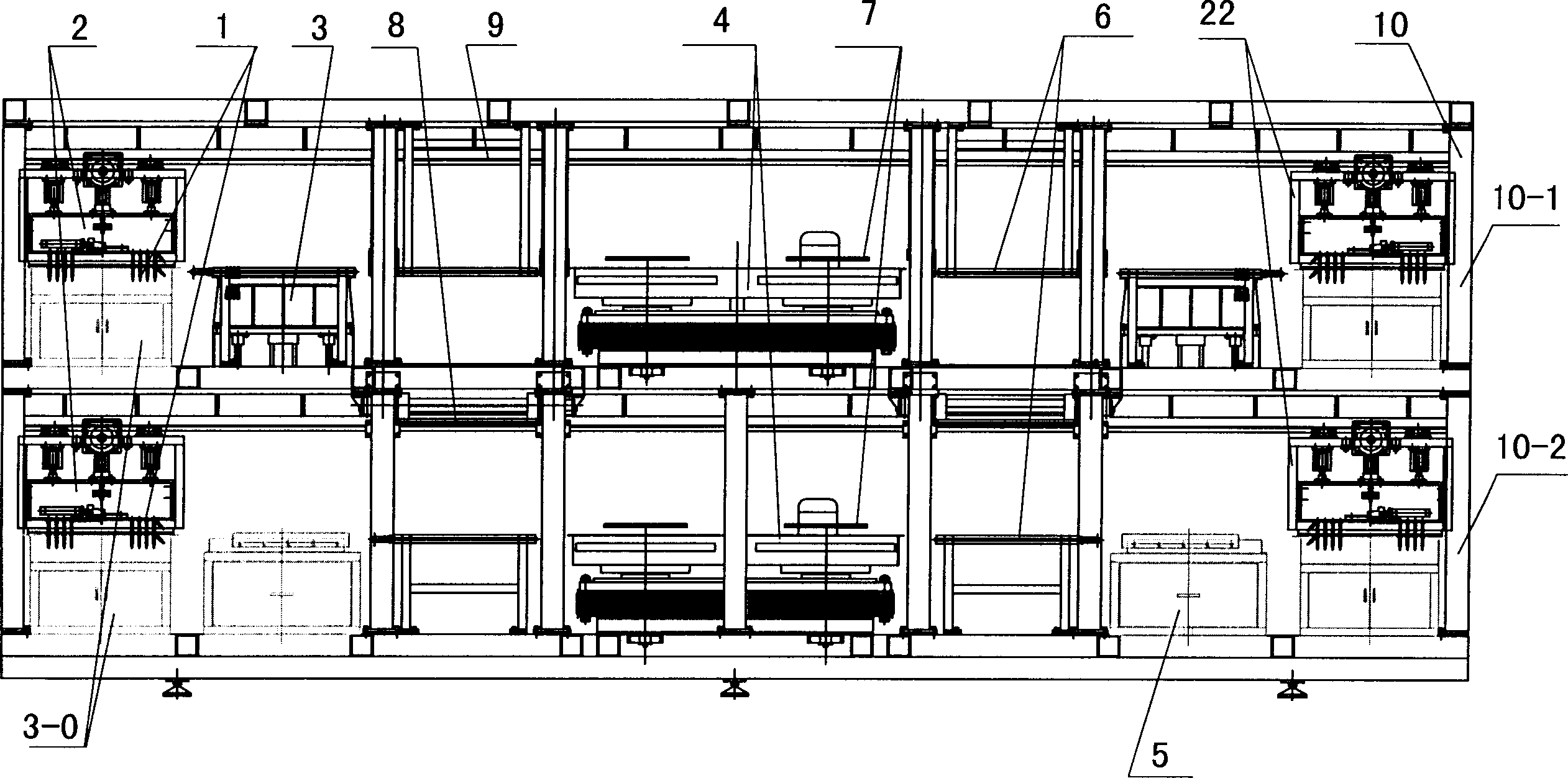
[0026] like figure 1 , 2 As shown, the fully automatic grinding and drilling machine of the present invention includes a sticking rod fixture 1 for fixing the ball blank, a fixture indexing mechanism 2 and a fixture frame 22, a powder holding component 3-0, a feeding device 3, a grinding / polishing wheel 4, a blanking The device 5, the heating mechanism 6, the water supply mechanism 7 and other components are characterized in that: the fully automatic grinding and drilling machine is also equipped with a fixture turning mechanism 8 and a fixture rack conveying mechanism 9;

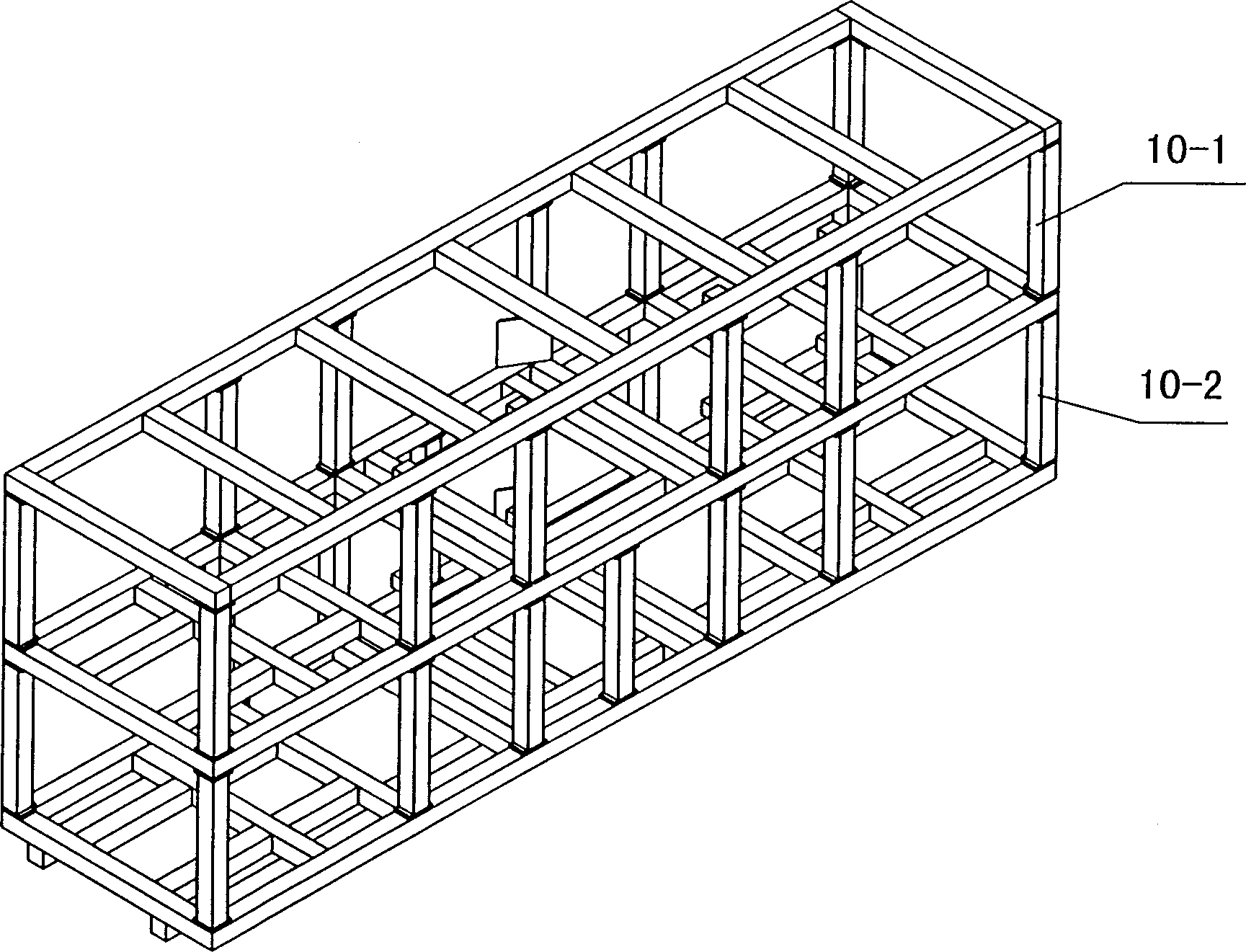
[0027] The fully automatic grinding and drilling machine is also equipped with a frame 10 composed of a beam and a vertical column. All the components of the fully automatic grinding and drilling machine, including the fixture turning mechanism 8 and the fixture frame conveying mechanism 9, are installed on the frame 10. On the beam and the column on the upper frame; the fixture rack conveying mechanism 9 ...


PUM


Abstract

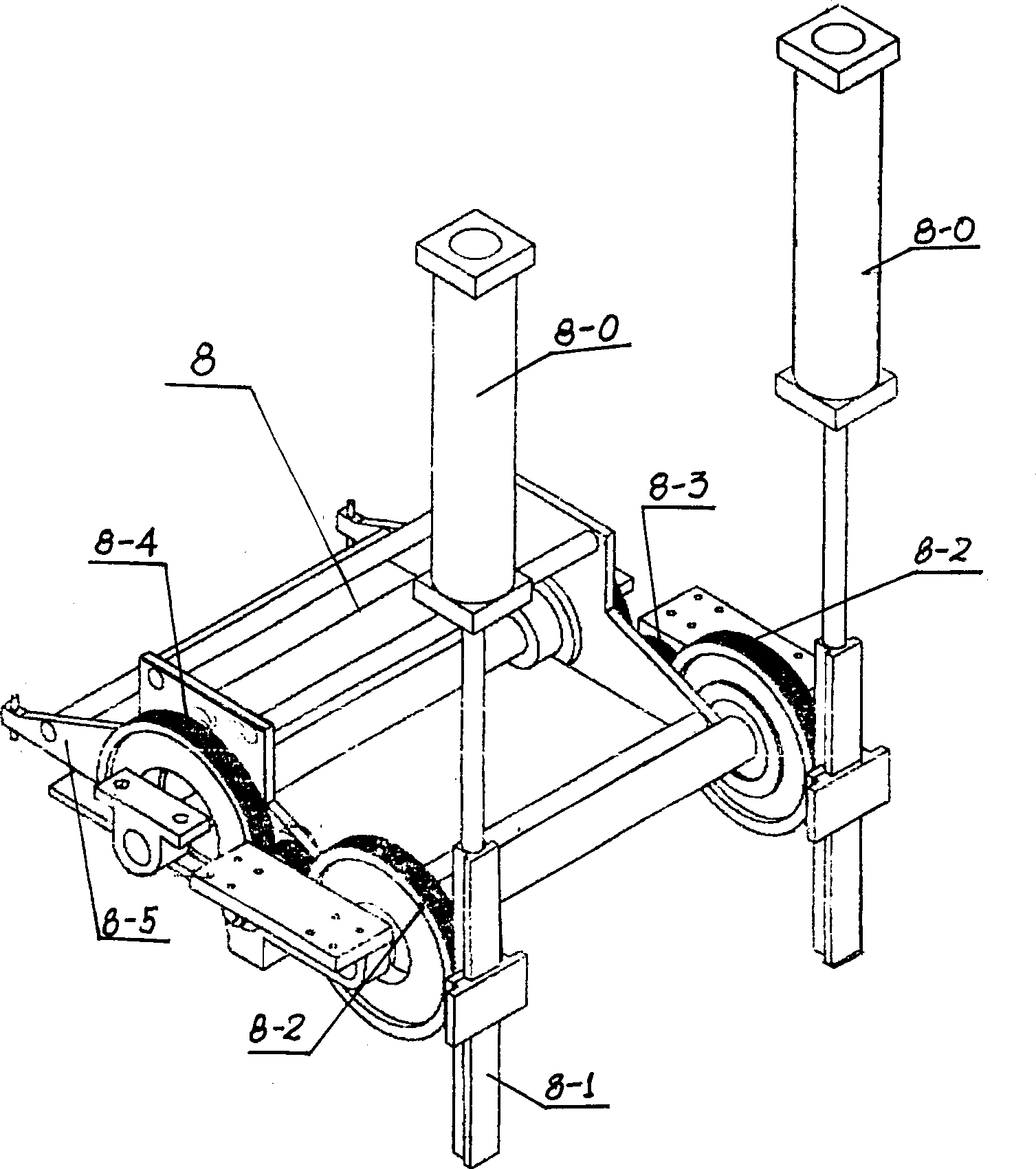
The autoamtic grinding and drilling machine includes adhesive rod fixture to fix ball blank, fixture indexing mechanism and stand, feeder, grinding and polishing wheel, discharger, heating mechanism and water supply mechanism, is characterized by fixture turnover mechanism and fixture stand conveying mechanism on the frame. The fixture stand conveying mechanism includes rails and gear rack mounted to the beam and upright of the frame; and the fixture turnover mechanism comprises gear pair and turnover support capable of moving horizontally and vertically to drive the fixture to turn. The fixture indexing mechanism includes spherical hinge in the middle section of the adhesive rod, cross gimbal and cylinder combination to drive the cross gimbal shift in several directions. The present invention has reasonable fixture structure.

Description

【Field of Invention】 [0001] The invention relates to grinding and polishing machinery, in particular to the field of machinery for grinding, polishing and shaping of diamonds or other high-hardness artificial gemstone ornaments. 【Background of Invention】 [0002] With the increasing improvement of people's living standards, more and more people, especially women, like to wear some real and fake treasures and decorative pieces made of diamonds to beautify themselves and their lives, while the hardness of real and fake treasures and diamond blanks is average They are tall and do not yet have an elegant shape, so they need to be sanded and shaped before they can be made into ornaments suitable for people to wear before they can be further assembled into marketable forms. In the past, this kind of grinding and shaping used a worm gear and worm-type indexing mechanism to control the rotation angle of the sticking rod fixture, and ground the ball blank with the circumferential sur...

Claims


Application Information

Patent Timeline
Patent Type & Authority Applications(China)
IPC IPC(8): B23Q3/00B24B9/16
Inventor 陈伟明邹庆原陈华
Owner 陈伟明
Learn More