Manufacture process of single ink jet head

An inkjet printing head and monomer technology, applied in the field of manufacturing inkjet printing heads, can solve the problems of photocurable polymer shape deformation, misalignment, nozzle clogging, etc.

Inactive Publication Date: 2003-05-14
SAMSUNG ELECTRONICS CO LTD
View PDF0 Cites 26 Cited by
  • Summary
  • Abstract
  • Description
  • Claims
  • Application Information

AI Technical Summary

Problems solved by technology

Secondly, since the thermal expansion coefficients of the nozzle plate 15 and the print head chip substrate 21 are different when the nozzle plate 15 is thermally bonded to the print head chip substrate 21, a mismatch will occur between the nozzle 15a and the heating element. positive situation
Third, the process of manufacturing inkjet printheads is very complex due to the need to perform an electroforming process, a two-step photoetching process, and a bonding process
However, this method has a limitation: it can only be used to manufacture inkjet printheads that work in side-firing
In addition, since this method requires a cutting process, the powder and particles generated during the cutting process may clog the nozzles and ink channels, and the shape of the photocurable polymer used to form the ink channels may also change during the cutting process. out of shape

Method used


Image

  • Manufacture process of single ink jet head
  • Manufacture process of single ink jet head
  • Manufacture process of single ink jet head

Examples


Embodiment Construction

[0037] Hereinafter, the present invention will be described in detail by describing preferred embodiments of the invention with reference to the accompanying drawings. However, the invention can also be implemented in many different ways and should therefore not be restricted by the examples cited. In the drawings, elements having the same function will be denoted by the same reference numerals, and the size and thickness of each element in the drawings are exaggerated for clarity. It can be understood that if a certain layer is said to be on another layer or on a substrate, this layer may be directly located on another layer or substrate, or may be interposed by other layers.

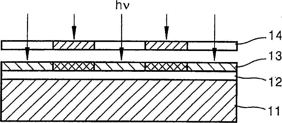
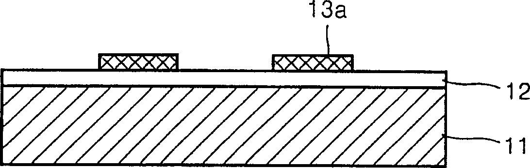
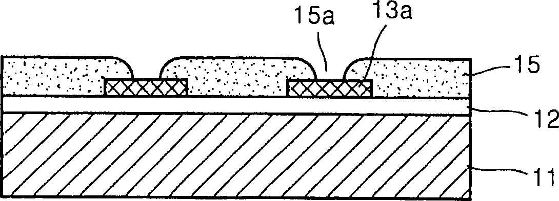
[0038] Figures 4A to 4E The various cross-sectional views in represent a method of making a monolithic inkjet printhead according to the present invention.

[0039] The method of manufacturing a monolithic inkjet printhead according to the present invention basically also uses a photolithographic pr...


PUM

PropertyMeasurementUnit
thicknessaaaaaaaaaa
thicknessaaaaaaaaaa
coating thicknessaaaaaaaaaa

Abstract

The present invention discloses a method of manufacturing a monolithic ink-jet printhead which includes a heating element which generates bubbles by heating ink is formed on a surface of the substrate, and a negative photoresist which is coated to a predetermined thickness on the substrate on which the heating element is formed. Next, a portion, which forms a sidewall of an ink passage forming wall surrounding an ink chamber and a restrictor, of the negative photoresist is flush exposed to light and cured using a first photomask in which patterns of the ink chamber and the restrictor of the ink passage are formed. Subsequently, a second portion which forms an upper wall of the ink passage forming wall of the negative photoresist is exposed to the light using a second photomask in which the pattern of a nozzle is formed, and the second portion is exposed to the light by only a predetermined thickness. Last, an uncured portion of the negative photoresist is dissolved and removed using solvent. An ink-jet printhead whose elements are monolithically formed by a simplified process using a single negative photoresist can be manufactured.

Description

technical field [0001] The present invention relates to a method of making an inkjet printhead, and more particularly, the present invention relates to a method of making a monolithic inkjet printhead using a negative photoresist. Background technique [0002] In general, an inkjet print head is a device that prints out an image in a set color by ejecting fine printing ink droplets to a desired position on a recording medium. In such an inkjet printhead, ink is delivered from an ink reservoir to an ink chamber through an ink supply hole and a flow restrictor. The ink filled in the ink chamber is heated by a heating element installed in the ink chamber, and is ejected from several nozzles in the form of droplets under the pressure of the bubbles generated by the heating element. [0003] Generally, since an inkjet printhead is to achieve high definition and high printing speed, it is necessary to arrange a plurality of nozzles in a highly integrated manner in its structure. ...

Claims


Application Information

Patent Timeline
Patent Type & Authority Applications(China)
IPC IPC(8): B41J2/16B41J2/05B41J2/17G03F7/00
CPCB41J2/1639B41J2/1646G03F7/038B41J2/1642G03F7/2022B41J2/1631B41J2/1629B41J2/1603B41J2/1645B41J2/17
Inventor 金泰均曹瑞铉郑明松金敬镒朴性俊
Owner SAMSUNG ELECTRONICS CO LTD
Why Eureka
Try Eureka