
Method and equipment for producing pressure wave

A pressure wave and generator technology, applied in the field of periodic pressure wave generation, can solve problems such as affecting reliability and efficiency, difficulty in processing and assembly, and performance degradation of refrigerators, so as to improve reliability and efficiency, reduce manufacturing costs, The effect of preventing pollution

Inactive Publication Date: 2003-06-04
TECHNICAL INST OF PHYSICS & CHEMISTRY - CHINESE ACAD OF SCI
View PDF0 Cites 5 Cited by
  • Summary
  • Abstract
  • Description
  • Claims
  • Application Information

AI Technical Summary

Problems solved by technology

Generally, there is a lot of friction between the piston and cylinder of this pressure wave generator due to the difficulty in processing and assembly, which seriously affects its reliability and efficiency
In addition, due to the high precision of machining and installation of the cylinder piston, the cost is high
In particular, when such a pressure wave generator is used in a regenerative cryogenic refrigerator, the performance of the refrigerator is often degraded due to iron pins generated by friction and outgassing contamination of internal materials.

Method used


Image

  • Method and equipment for producing pressure wave
  • Method and equipment for producing pressure wave
  • Method and equipment for producing pressure wave

Examples


Embodiment 1

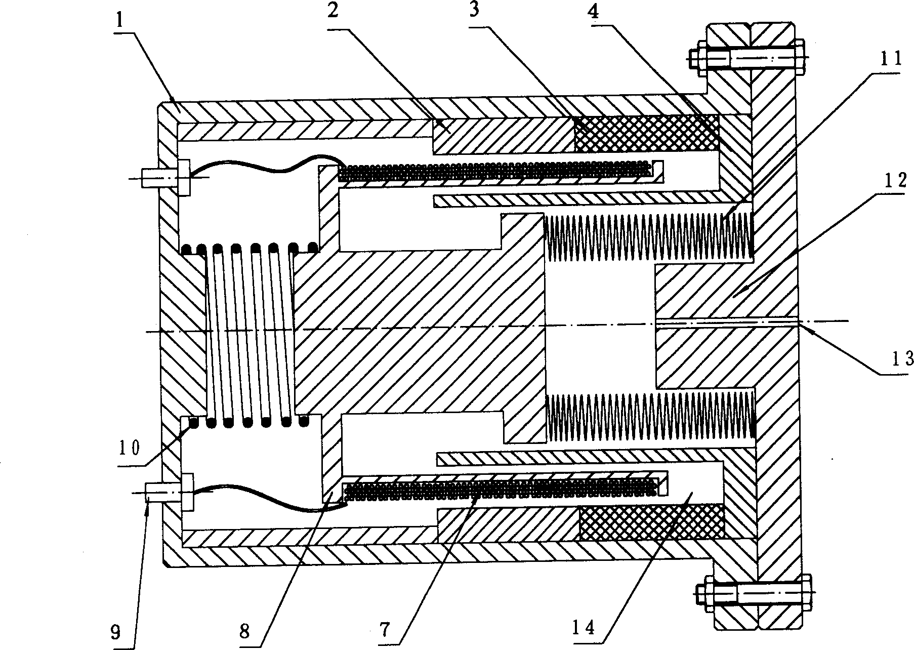
[0026] Example 1: Press figure 2 Make a single-drive pressure wave generator

[0027] The shell 1 of the pressure wave generator is made of alloy aluminum, its purpose is to reduce weight and enhance heat exchange; the permanent magnet 3 is made of NdFeB material with higher magnetic energy level, which can be generated in the slit 14 of the magnetic field circuit to reach The magnetic field strength between 1-1.3T (Tesla) is beneficial to reduce the current on the moving coil 7 of the coil, thereby reducing the Joule heat loss in the coil. The magnetizer A-2 and the magnetizer B-4 are made of DT4 electrical pure iron. The moving coil frame 8 is formed by winding a high-insulation copper wire with a diameter of 1-3 mm on a mountain-shaped alloy aluminum frame. The compressible metal corrugated bellows 12 is welded by multi-layer stainless steel sheet (the market has stereotyped products can choose) between thickness 0.1-0.2 millimeter. The moving coil skeleton 8 and the me...

Embodiment 2

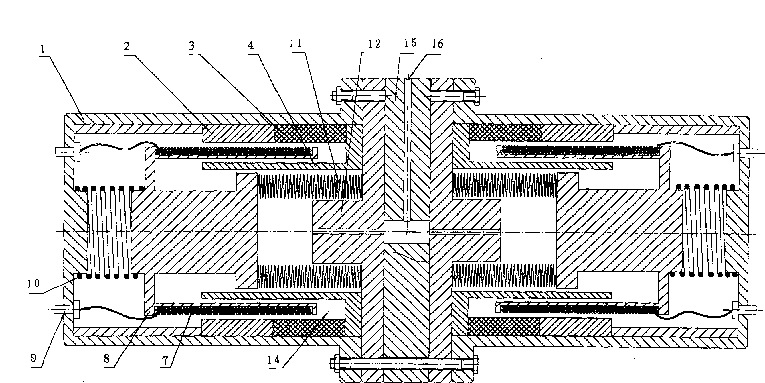
[0033] Example 2: Press image 3 Making a Dual Drive Opposed Pressure Wave Generator

[0034] The material and manufacturing process of the relevant parts of the pressure wave generator are basically the same as those in Implementation 1, except that a pressure wave generator is added, and the left and right sides are connected by a connecting part 15 made of duralumin between the two pressure wave generators. The single pressure wave generator is fixed as a whole, and a channel 16 is processed in the radial direction of the connecting part 15, which is the pressure wave output port. The radially processed channel 16 communicates with the channel 13 of the cylinder 12 of the pressure wave generator . Because the pressure wave generator is bilaterally symmetrical, its vibration and noise are extremely small, and it is more widely used in regenerative refrigerators.


PUM

PropertyMeasurementUnit
Thicknessaaaaaaaaaa

Abstract

The present invention relates to pressure wave generator and pressure wave producing method. The pressure wave generator includes one casing with lug and binding post; one support spring installed onthe lug, one moving coil skeleton with wound copper wire, one metal membrane box and one cylinder with one central passage connected to outer use part connected successively; magnetic conductor A andone permanent magnet installed successively on the upper part of the casing cavity, and one magnetic conductor sleeve B with edge pressing the permanent magnet and inserted into the slot of the moving coil skeleton. Under the action of alternate current, electromagnetic driving mechanism pushes the metal membrane box to reciprocate and the gas pressure inside the membrane box becomes high and lowperiodically, so that pressure wave is output outwards.

Description

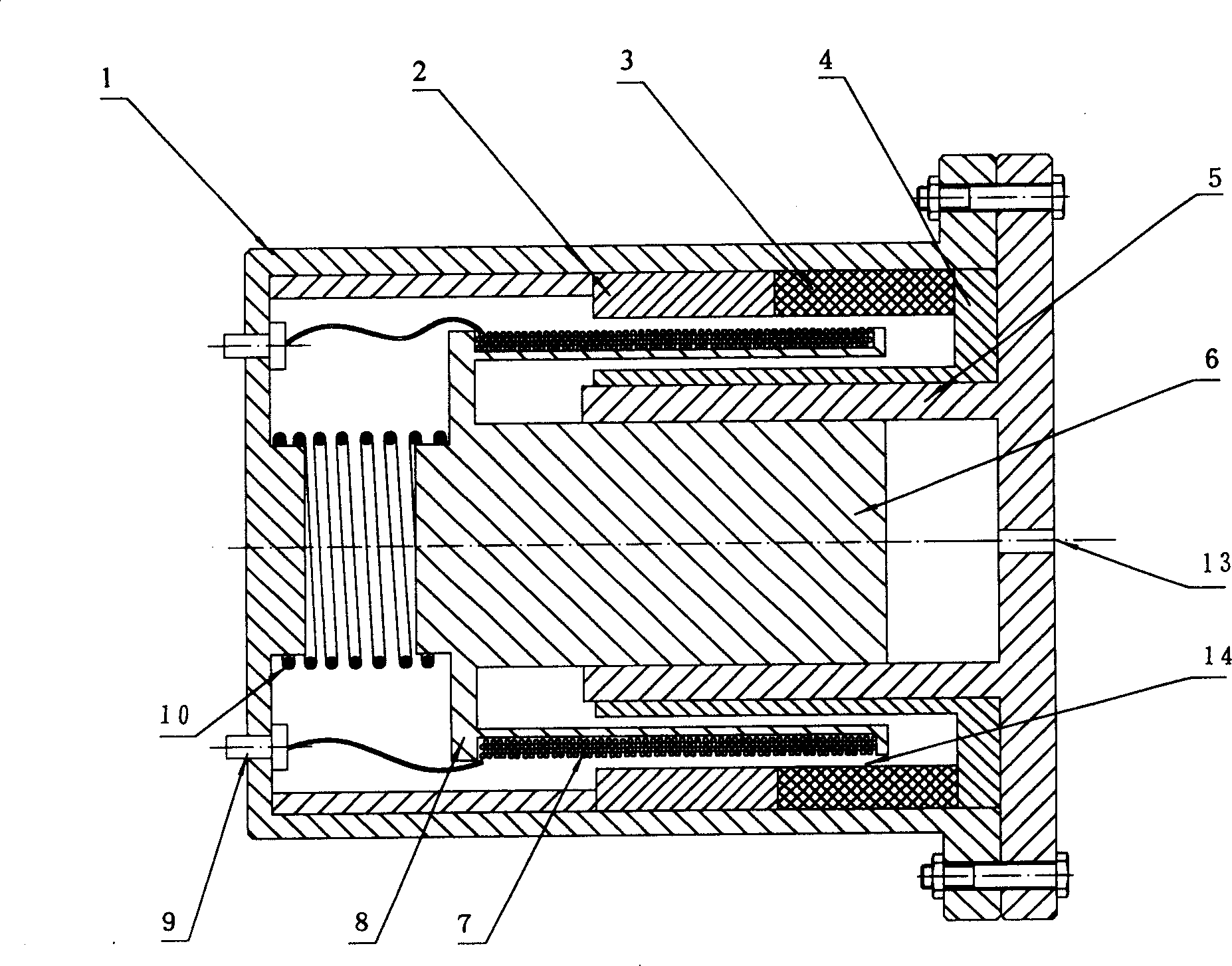
technical field [0001] The invention relates to a method for generating periodic pressure waves and its special device, in particular to a method for generating pressure waves by using a compressible metal corrugated bellows to periodically change volume under electromagnetic driving force and its special device. device. Background technique [0002] Pressure wave generators are widely used in industry, especially in low temperature regenerative refrigerators. At present, the pressure wave generator driven by electromagnetic oscillation to reciprocate the cylinder piston is as described in the literature [1]: Yu Yongzhang, edited by Liu Yong, Special Compressors: Power, Chemical and Refrigeration; Beijing, Mechanical Industry Press, 1989. : It is directly driven by alternating current to generate reciprocating driving force to drive the piston to reciprocate; figure 1 As shown: it mainly includes permanent magnet (3), magnetizers A, B (2, 4), moving ...

Claims


Application Information

Patent Timeline
IPC IPC(8): F04B43/09F25B9/00F25B9/02
Inventor 罗二仓吴剑峰胡勤国公茂琼
Owner TECHNICAL INST OF PHYSICS & CHEMISTRY - CHINESE ACAD OF SCI
Features
  • Generate Ideas
  • Intellectual Property
  • Life Sciences
  • Materials
  • Tech Scout
  • Unparalleled Data Quality
  • Higher Quality Content
  • 60% Fewer Hallucinations
Learn More