
Structure and part for electric cable connection and making method thereof

A technology for electrical connection and power cable, which is applied in the direction of cable joints, cable accessories, cable installation, etc., and can solve the problems of increasing the length and size, the overall length of the connecting part, and increasing the manufacturing cost.

Inactive Publication Date: 2003-06-11
THE FUJIKURA CABLE WORKS LTD
View PDF0 Cites 8 Cited by
  • Summary
  • Abstract
  • Description
  • Claims
  • Application Information

AI Technical Summary

Problems solved by technology

[0015] In addition, in the above-mentioned connection part PM100, such as Figure 10B As shown, the outer electrode 131 is formed as a pressure cone for large-radius electric field control. The function of the pressure cone is only limited to the shape integration with the shielding screen 6. However, due to the large thickness and corresponding increase in length, the connection The overall length of the part becomes longer
[0016] In this way, the manufacturing cost is increased. Therefore, it is desired to have a connection structure or a connecting part of the power cable that can reduce the manufacturing cost.

Method used


Image

  • Structure and part for electric cable connection and making method thereof
  • Structure and part for electric cable connection and making method thereof
  • Structure and part for electric cable connection and making method thereof

Examples


Embodiment Construction

[0060] The above and other objects, features, functions and effects of the present invention are referred to below Figure 1-Figure 8 The description of the examples will be more clear. In the drawings, the same elements are denoted by the same reference numerals.

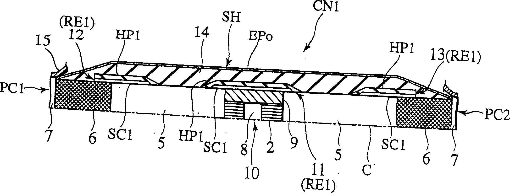
[0061] figure 1 The connection structure CN1 of the plastic insulated power cables PC1, PC2 related to the first embodiment of the present invention is shown.

[0062] This connection structure CN1 is composed of: the core wire connection part 10 electrically connecting the exposed conductor cores 2, 2 of the left and right power cables PC1 and PC2, and connecting the exposed shielding screens 6, 6 of the power cables PC1 and PC2. The shield connection portion SH for electrical connection between these core wire connection portions 10 and the shield connection portion SH is used to form the exposed insulating cross-linked polyethylene insulators 5 and 5 of the power cables PC1 and PC2 filled between these core w...


PUM


Abstract

A cylindrical pre-molded rubber insulation tube made by a plurality of layers using a rubber material as a base material has in a central part and at both ends of an inner periphery thereof a sheet-shaped electrode layer formed at an insde thereof with a semi-conductive rubber layer and at an outside thereof with a high-permittivity rubber layer, as an inner electrode layer configured with the semi-condutctive rubber layer to be thin and sheet-shaped and the high-permittivity rubber layer covering a vicinity of a respective distal end of the semi-conductive rubber layer, and the distal end of the semi-conductive rubber layer is rounded by a radius of curvature substantially equal to half the thickness.

Description

technical field [0001] The invention relates to a connection structure, a connection component and a manufacturing method of the connection component for electrical connection of power cables. Background technique [0002] The power cable is a conductor core formed by a bundle of core wires that transmit the required power, an insulator made of plastic materials such as cross-linked polyethylene to insulate the surroundings of the above-mentioned conductor cores, and a shielding screen that shields the surroundings of the above-mentioned insulators It is composed of a coat covering and protecting the surrounding of the above-mentioned shielding screen. [0003] Therefore, in order to realize the electrical connection of the power cable, it is necessary to have a connection structure having connection elements with functions of power transmission, insulation, shielding and coating protection respectively. In particular, it is necessary to be able to reliably prevent failures...

Claims


Application Information

Patent Timeline
Patent Type & Authority Applications(China)
IPC IPC(8): H02G15/103H02G15/184
CPCH02G15/103H02G15/184
Inventor 新延洋渡边和夫
Owner THE FUJIKURA CABLE WORKS LTD
Learn More