Light catalyst reaction device and processing technique for continuous degrading waste water containing organic contamination

A technology for photocatalytic reaction and organic pollutants, which is applied in the field of high-efficiency photocatalytic reaction devices and its treatment, can solve the problems of short light residence time of wastewater to be treated, reduced photocatalytic efficiency and activity, and difficult separation and recovery of catalysts, etc., to achieve increased The wastewater treatment capacity, the depth of degradation can be adjusted, and the effect of prolonging the reaction residence time

Inactive Publication Date: 2003-07-23
NANJING UNIV OF TECH
View PDF4 Cites 20 Cited by
  • Summary
  • Abstract
  • Description
  • Claims
  • Application Information

AI Technical Summary

Problems solved by technology

[0005] Both of these two reactors have the problems of short residence time of wastewater to be treated, low effective utilization of light, and low reactor efficiency.
In addition, if the catalyst uses nano-powder, there is a problem that the catalyst is difficult to separate and recover. If the catalyst is fixed on the carrier, its photocatalytic efficiency and activity will be seriously reduced.

Method used


Image

  • Light catalyst reaction device and processing technique for continuous degrading waste water containing organic contamination
  • Light catalyst reaction device and processing technique for continuous degrading waste water containing organic contamination
  • Light catalyst reaction device and processing technique for continuous degrading waste water containing organic contamination

Examples


Embodiment 1

[0031] Put the whiskers of potassium tetratitanate into 100 times the mass of water, and continuously add sulfuric acid to exchange potassium ions with hydrogen ions in the solution. The acidity meter controls the pH of the solution to 1, and after fully reacting, wash with water until neutral , sintered at 500 °C for 2 h to prepare fibrous TiO 2 catalyst. XRD analysis shows that it is anatase TiO 2 . Its average diameter: 0.5-3.0 μm, length: 5-100 μm.

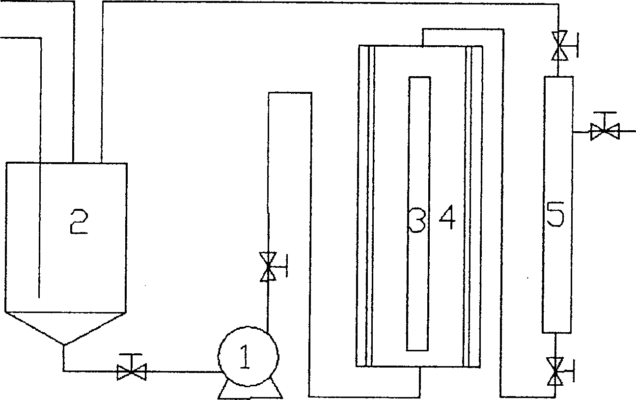
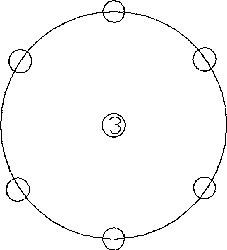
[0032] The photoreactor adopts 6 photoreaction tubes to be parallel and evenly distributed around the lamp tube 3, the distance between the lamp tube and the photoreaction tube is 150mm, the diameter of the photoreaction tube is 25mm, and the length of the lamp tube and the photoreaction tube is 1000mm.

[0033] The wastewater treatment process flow of the present invention is as described above.

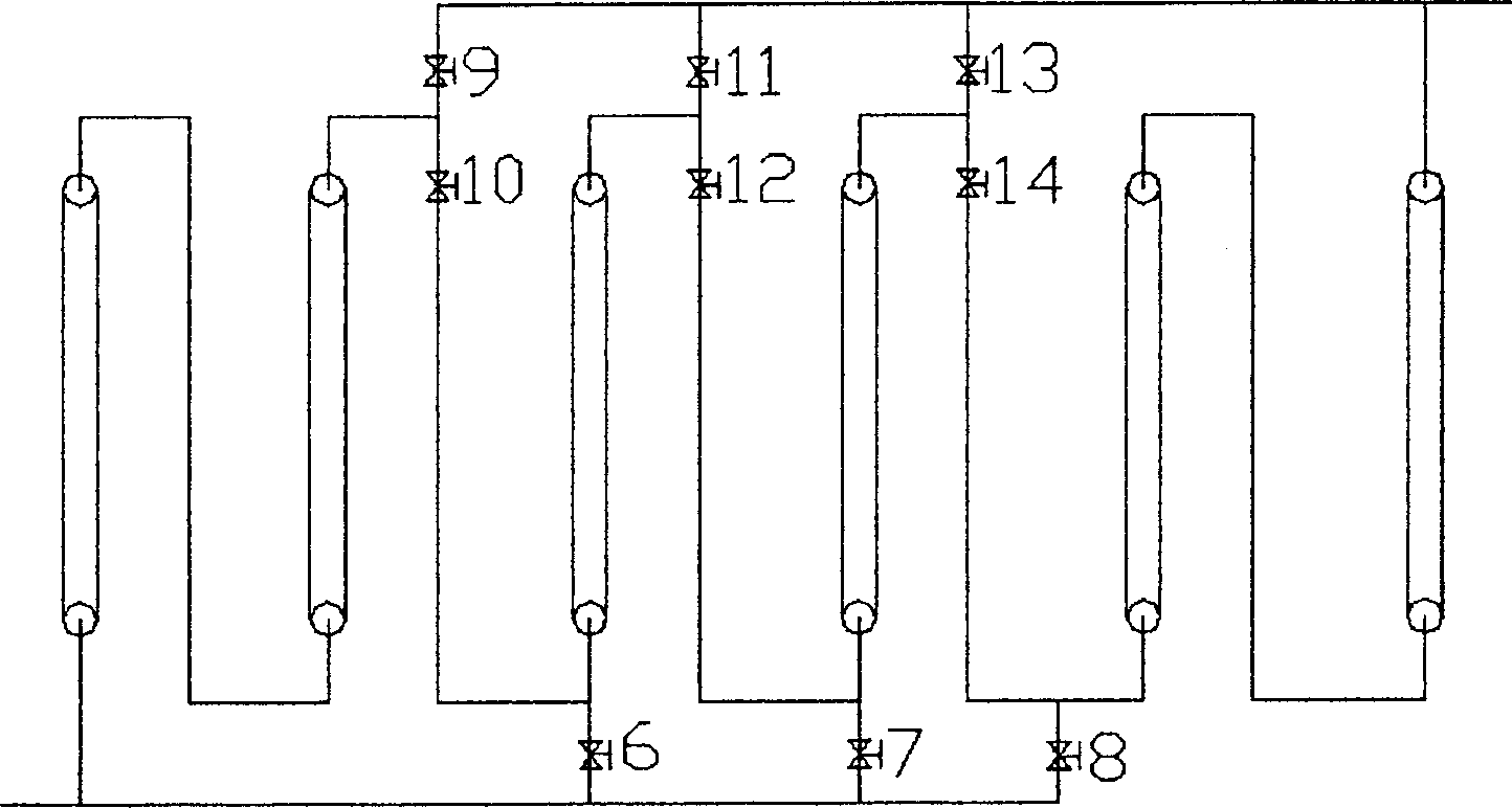
[0034] closure figure 2 Middle valves 6, 7, 8, 9, 11, 13, open valves 10, 12, 14, put the photoreaction tubes in series, us...

Embodiment 2

[0039] Add 5 g of the catalyst in Example 1 into a chloroplatinic acid solution equivalent to 0.5 wt % of the catalyst amount, then add 50 ml of 2-propanol, illuminate with a 300 W medium-pressure mercury lamp for 3 h under stirring, filter and dry, and obtain a deposit of 0.5 Modified fibrous TiO with wt% platinum 2 as a catalyst. Close the valves 6, 7, 8, 9, 11, 13, open the valves 10, 12, 14, make the photoreaction tubes in series, use the initial concentration of 1mmol / L chloroform solution as the waste water to be treated, add the catalyst concentration to be 0.5g / L, through oxygen bubbling, the pump flow rate is 40L / h, and the degradation rate of chloroform in the wastewater discharged after light is 98%.

Embodiment 3

[0044] Commercial TiO produced by Beijing Chemical Plant 2 The photocatalytic reaction was carried out after activation at a constant temperature of 500°C for 2h. Close valves 7, 10, 11, 14, open valves 6, 8, 9, 12, 13, make the photoreaction tubes in 2 series and 3 parallel states, use the methyl orange solution with an initial concentration of 5mg / L as the wastewater to be treated, Added prooxidant H 2 o 2 The concentration is 3ml / L, the pump flow rate is 120L / h, and the degradation rate of methyl orange in the wastewater discharged after illumination is 47%.


PUM

PropertyMeasurementUnit
lengthaaaaaaaaaa
diameteraaaaaaaaaa
thicknessaaaaaaaaaa

Abstract

A photocatalytic reactor equipment with granular or fibrous semiconductor material as catalyst for continuously degradating toxic organic sewage is composed of optical reactor, filter, pump and buffering tank. Its advantages are easy recovery of catalyst, high reaction efficiency, high optical utilization rate, and high treating capacity.

Description

Technical field: [0001] The invention relates to a high-efficiency photocatalytic reaction device and its treatment technology, which are characterized in that the catalyst is easy to recycle, the efficiency of the reactor is high, the effective utilization rate of light is high, the wastewater treatment capacity and degradation depth can be adjusted, and it can continuously degrade Degradation of toxic organic pollutants in wastewater. technical background: [0002] For toxic organic pollutants that are difficult to degrade, such as organic halogenated hydrocarbons, polychlorinated biphenyls, organophosphorus compounds, polycyclic aromatic hydrocarbons, etc., traditional wastewater treatment technologies such as physical and chemical methods, biochemical methods, etc. have technical and economic advantages. How to deal with these refractory, carcinogenic and mutagenic organic pollutants in water quality has become an urgent problem to be solved in today's environmental prot...

Claims


Application Information

Patent Timeline
Patent Type & Authority Applications(China)
IPC IPC(8): C02F1/30C02F1/32
CPCY02W10/37
Inventor 陆小华杨祝红冯新郑仲陈国钧朱健史月萍
Owner NANJING UNIV OF TECH
Why Eureka
Try Eureka