Axial plunger type water hydraulic pump

A water-hydraulic, axial-column technology, applied in the direction of pumps, multi-cylinder pumps, liquid displacement machinery, etc., can solve the problems of design and manufacturing difficulties, low volumetric efficiency, large leakage, etc., to avoid sticking and jamming Dead, low noise, reliable sealing effect

Inactive Publication Date: 2003-08-06
HUAZHONG UNIV OF SCI & TECH
View PDF0 Cites 46 Cited by
  • Summary
  • Abstract
  • Description
  • Claims
  • Application Information

AI Technical Summary

Problems solved by technology

The disadvantage is: the end face flow distribution pair (cylinder end face and flow distribution plate) is a pair of high-speed, heavy-duty friction pairs. Under the condition of water lubrication, to achieve reliable work an

Method used


Image

  • Axial plunger type water hydraulic pump
  • Axial plunger type water hydraulic pump
  • Axial plunger type water hydraulic pump

Examples


Embodiment Construction

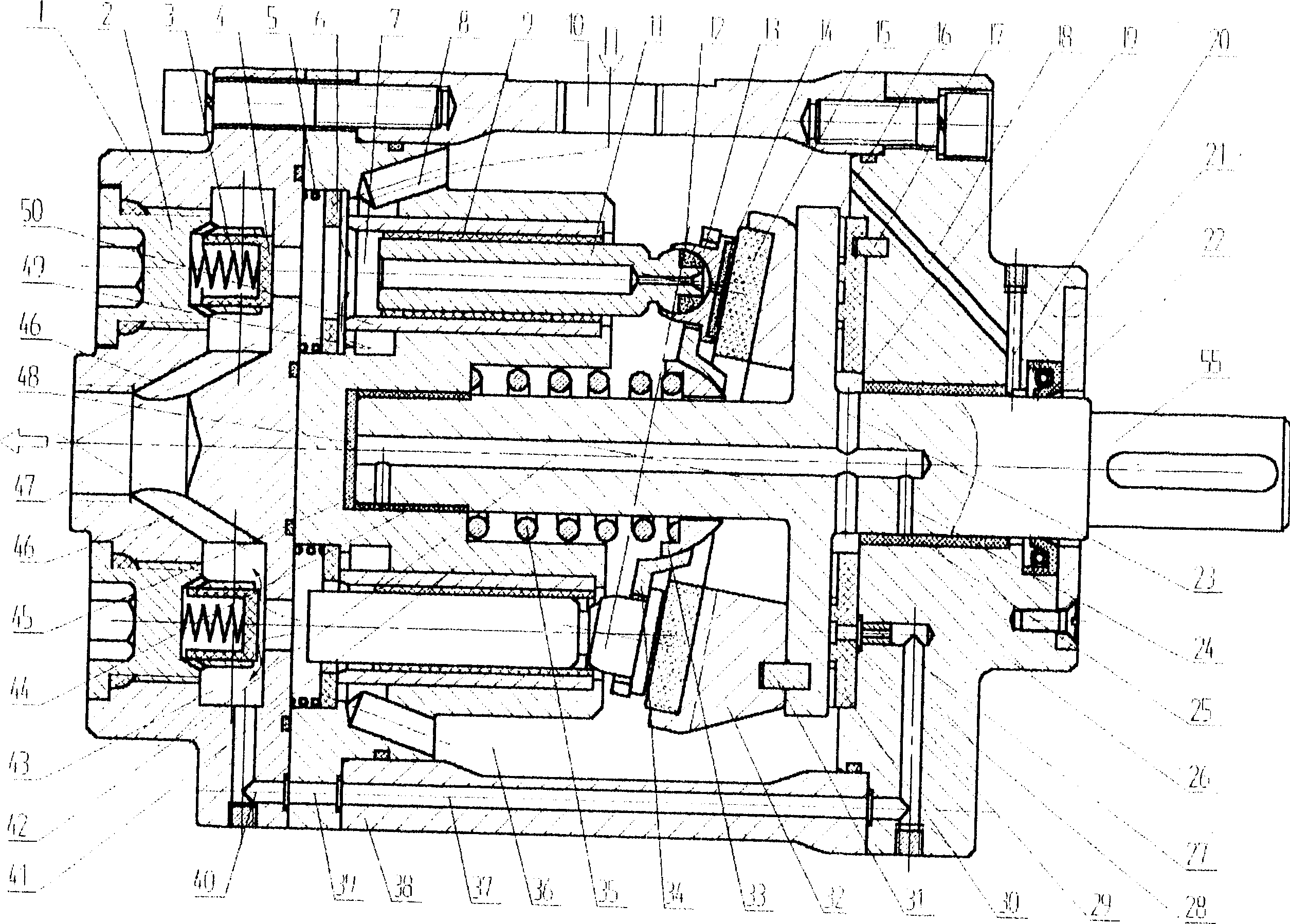
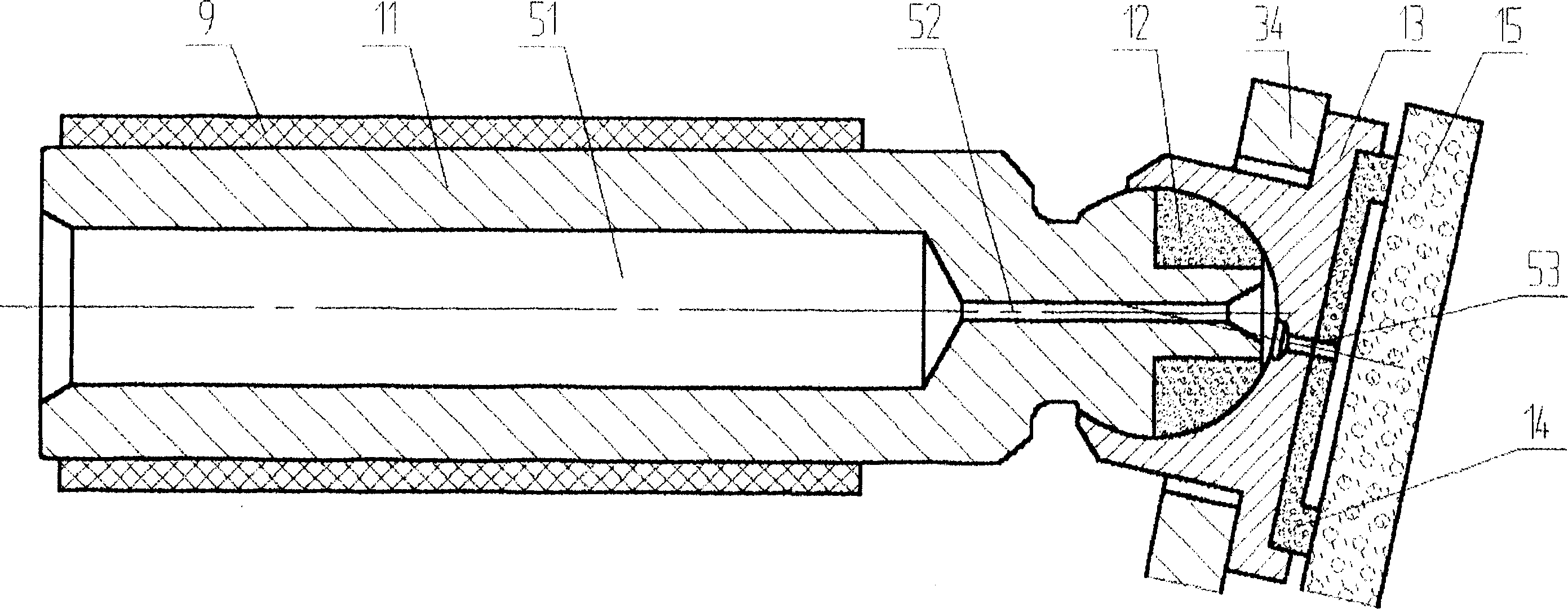
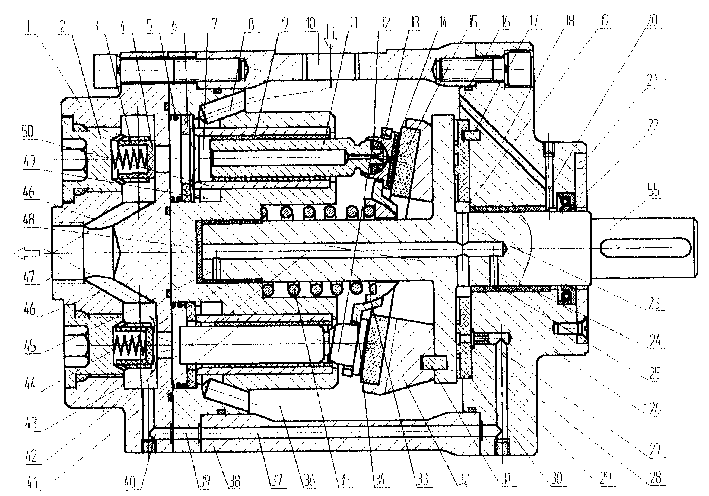
[0024] refer to Figure 1 ~ Figure 2 , the water hydraulic pump consists of a rear end cover 1, a discharge valve (composed of a discharge valve body 2, a discharge valve spring 3 and a discharge valve core 4), a suction valve (composed of a suction valve spring 5 and a suction valve core 6 ), cylinder block 41, pump housing 38, plunger shoe assembly (composed of plunger 11, hemispherical head 12, shoe 13 and shoe sole 14), friction plate 15, swash plate 32, center spring 35, ball hinge 33 , Return disc 34, thrust disc 16, main shaft 55, thrust bearing 30, front end cover 26, front sliding bearing 25, rear sliding bearing 44, shaft seal 22 and shaft seal cover 21 etc. constitute.

[0025] Several (such as 5, 7 or 9) plunger holes 7 parallel to the axis of the cylinder body (axial) are evenly distributed in the circumferential direction of the cylinder body 41, and the outer metal cylinder sleeve 50 and the inner plastic cylinder sleeve are embedded in the plunger holes. 9. Th...


PUM


Abstract

The axial plunger water hydraulic pump is characterized by that it adopts plate value to make flow distribution, the plunger and plunger hole are axial uniformly distributed on the periphery relativeto main shaft, it utilizes an oblique plate and central spring to implement reciprocation of plunger, the plunger, plunger bulb and slipper are equipped with central holes respectively, and on the rear end cover, cylinder body, pump shell and front end cover the flow passages are cut, and the central position of thrust bearing has a ring chavity chamber, interior of the main shaft is equipped with an axial flow passage, and its surface is equipped with a radial flow passage, all the flow passage are communicated to directly water lubricate and cool all the friction pairs.

Description

technical field [0001] The invention belongs to liquid variable capacity machines and pumps. Background technique [0002] The water hydraulic transmission technology that directly uses natural seawater or fresh water as the hydraulic medium has the characteristics of safety, compatibility with the environment, compatibility with products, system simplification, energy saving, economy, and sanitation, and can satisfy people's needs for safety, economy, and the environment to the greatest extent. The desire for protection and other aspects meets the needs of sustainable development of human beings, and has become a frontier topic in the field of international hydraulic technology today, with extremely broad application prospects. Developed countries including the United States, Britain, Germany, Finland, Denmark, Japan, etc. began to develop it in the late 1970s or early 1980s, and now it has entered the stage of practical promotion. It has been used in mining industry, steel...

Claims


Application Information

Patent Timeline
IPC IPC(8): F04B1/12
Inventor 杨曙东李壮云朱玉泉
Owner HUAZHONG UNIV OF SCI & TECH
Why Eureka
Try Eureka