Filter having directional couplex and communication device

A directional coupler and filter technology, which is used in connection devices, waveguides, waveguide-type devices, etc., can solve the problems of inability to form directional couplers between resonators, insufficient coupling line length, and directivity restrictions.

Inactive Publication Date: 2003-08-06
MURATA MFG CO LTD
View PDF4 Cites 21 Cited by
  • Summary
  • Abstract
  • Description
  • Claims
  • Application Information

AI Technical Summary

Problems solved by technology

[0024] Therefore, sufficient coupling line length cannot be obtained, and the directivity that can be achieved is limited
[0025] In addition, in the band-pass filter, the main structure is to obtain the band-pass characteristic through the coupling between the resonators constituting the filter. In such an element, since there is no main line part, the resonator Directional couplers that cannot form coupled lines
[0026] In addition, in the band-stop filter, the commonly used structure is to connect the resonator with a line of 1 / 4 wavelength length of the transmission signal, but because complex standing waves are generated inside the filter, even if simply using two parallel Conductors form coupled lines, and good directivity cannot be obtained

Method used


Image

  • Filter having directional couplex and communication device
  • Filter having directional couplex and communication device
  • Filter having directional couplex and communication device

Examples


Embodiment Construction

[0168] Embodiment 1

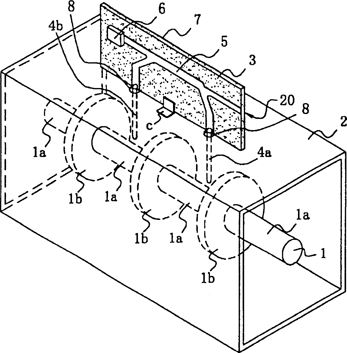
[0169] Refer below figure 1 The configuration of a filter with a directional coupler according to the first embodiment will be described.

[0170] figure 1 A partial perspective view of a low-pass filter with a directional coupler.

[0171] exist figure 1 Among them, 1 is the inner conductor, 1a is the high impedance part, 1b is the low impedance part, 2 is the outer conductor, 3 is the dielectric substrate, 4a and 4b are the probes of the coupling element, 5 is the coupling line, 6 is the resistor, 7 8 is a hole for probe insertion, 20 is an output end of a coupling end, and c is an installation metal part.

[0172] The inner conductor 1 is integrally formed in a shape in which high-impedance portions 1a and low-impedance portions 1b are alternately connected. The inner conductor 1 is arranged at the center of the outer conductor 2 having a substantially square cross section. Two holes penetrating the side wall of the outer conductor 2 are forme...


PUM


Abstract

The present invention configures a filter with directional coupler which has superior attenuation characteristics and can provide satisfactory directivity in a simple structure. An inner conductor 1 having such a shape as alternately linking high impedance parts 1a and low impedance parts 1b is located in the center inside an outer conductor 2 having an approximately square cross section. On one lateral side of the outer conductor 2 (on the upper surface in a figure), two holes 8 through the wall of the outer conductor 2 are formed. On the surface of a dielectric substrate 3, an approximately [pi]-shaped line 5 for coupling composed of a main line part and a probe connection part is formed and probes 4a and 4b formed from conductive rods are connected to the end parts of the line 5. A resistor 6 is provided in one end of the main line part of the line 5 for coupling. The other end can connect an external circuit as an output terminal 20. The probes 4a and 4b are inserted into the holes 8 and the dielectric substrate 3 is installed at a prescribed position inside the outer conductor 2.

Description

technical field [0001] The present invention relates to a filter and a directional coupler for microwave communication, in particular to a filter with a built-in directional coupler, a composite filter device having a filter with a directional coupler, and a communication device. Background technique [0002] Generally, a filter is provided in the preceding stage of the communication device, and a directional coupler is also provided in order to check the operation status of the communication device. FIG. 18 is a block diagram of a conventional communication device such as a mobile phone. [0003] In Figure 18, the power amplifier amplifies the power of the transmitted signal, and the low-pass filter attenuates the high-order filter components. The directional coupler outputs a part of the transmission signal to the antenna transmission power monitoring device. The antenna transmission power monitoring device adjusts the output of the power amplifier after detecting the in...

Claims


Application Information

Patent Timeline
Patent Type & Authority Applications(China)
IPC IPC(8): H01P1/202H01P1/203H01P1/205H01P1/208H01P5/18
CPCH01P1/20363H01P5/187H01P1/20381H01P1/205H01P1/202H01P5/185H01P1/2039H01P5/18
Inventor 角田紀久夫竹井泰範伊藤宏充
Owner MURATA MFG CO LTD
Why Eureka
Try Eureka