Pilot-actuated valve

A pilot valve and valve technology, applied in the field of pilot valves, can solve the problem of high production cost of valve closing components and connecting rods, and achieve the effect of reducing flow force

Inactive Publication Date: 2003-08-13
CATERPILLER GLOBAL MINING EURO GMBH
View PDF1 Cites 9 Cited by
  • Summary
  • Abstract
  • Description
  • Claims
  • Application Information

AI Technical Summary

Problems solved by technology

The production costs of the valve closing element and the connecting rod forming the valve closing body are therefore relatively high, and the working capacity of a pilot valve of this type depends on the exact adjustment of the distance between the sealing seats of these two valves

Method used


Image

  • Pilot-actuated valve
  • Pilot-actuated valve
  • Pilot-actuated valve

Examples


Embodiment Construction

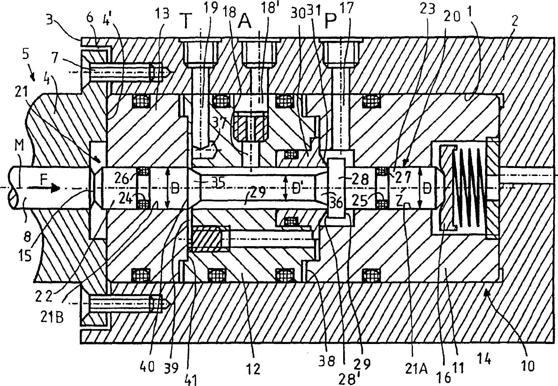
[0024] figure 1 It shows a vertical section through a valve opening 1 of a valve block 2 with possibly several valve openings arranged side by side and superimposed on one another. The valve mounting hole 1 is designed as a blind hole, into which the pilot valve 10 designed as a sleeve-like valve insert according to the first embodiment is inserted from the direction of the end side 3 of the valve block 2 . The valve insert constituting the pilot valve 10 has a valve housing divided into three parts, comprising a first valve housing part 11, a second valve housing part 12 and a third valve housing part 13, which pass through each other at their interface 38 or 41 respectively. They are screwed together and fixed together in the valve mounting hole 1 by means of the housing 4 of the switching device 5 which is only schematically indicated. The housing bottom 4 ′ of the switching device 5 is seated in a countersink 6 on the end side 3 , and its fastening flange protrudes beyond...


PUM


Abstract

The present invention relates to a pilot control valve, especially for use in mining hydraulics. The valve has a valve insert constructed as a valve cartridge, whose single or multipart valve housing has an input entry for pressure fluid, a connection opening for a load connection, an output opening, opening into the return flow and an axial boring to accept a valve closing body provided with a closing surface, which can be lifted from a valve sealing seat arranged between the entry opening and the connection opening by means of an electro-magnetic or piezo-electric switching device which can be fastened onto the valve housing. With the lifting movement of the valve closing body from the valve sealing seat is coupled an at least two part closing mechanism for their separation arranged between the connection opening and the output opening. In accordance with the present invention a single part valve closing body is provided, having the sealing surface in the form of a collar and the moving part of the closing mechanism in the form of a shaft section, whereby the shaft section enters into a boring section of the axial boring during the lifting movement, closing a radial opening. The valve sealing seat can be exchanged with a valve sleeve and the nominal bore of the pilot control valve can be changed by means of a throttle.

Description

technical field [0001] The invention relates to a pilot valve especially used in mine hydraulic equipment, comprising a valve insert that can be installed in a valve mounting hole of a valve block, etc., constitutes a multi-way valve and is designed as a valve sleeve (Ventilpatrone), its The valve housing has an inlet for pressurized liquid, a connection for the consumer, an outlet for the return line and an axial hole for mounting a valve closing body with a closing surface, which can be fixed by means of a The switching device on the valve housing overcomes the spring's return force and lifts up from a valve sealing seat that is located between the inlet and the connection port and is assigned to the closing surface. Closing mechanisms are incorporated in order to isolate them from the lifting movement of the valve closing body from the valve sealing seat. Background technique [0002] This type of pilot valve is mainly used to switch the main control valve located downst...

Claims


Application Information

Patent Timeline
Patent Type & Authority Applications(China)
IPC IPC(8): F15B13/042F15B13/02F15B13/04F15B13/043F16K11/048F16K27/02
CPCF16K27/0263F16K27/029Y10T137/86582Y10T137/86678F16K11/048
Inventor 弗朗茨-海因里希·苏伊尔曼帕特里克·汉特克塞巴斯蒂安·M·蒙德里托尔斯滕·博尔特
Owner CATERPILLER GLOBAL MINING EURO GMBH
Why Eureka
Try Eureka