Chemical processing device
A technology for chemical treatment and treatment of solution, applied in the directions of spraying device, spraying device, liquid spraying device, etc., to achieve the effect of compact treatment solution supply system
- Summary
- Abstract
- Description
- Claims
- Application Information
AI Technical Summary
Problems solved by technology
Method used
Image

Examples
no. 1 example
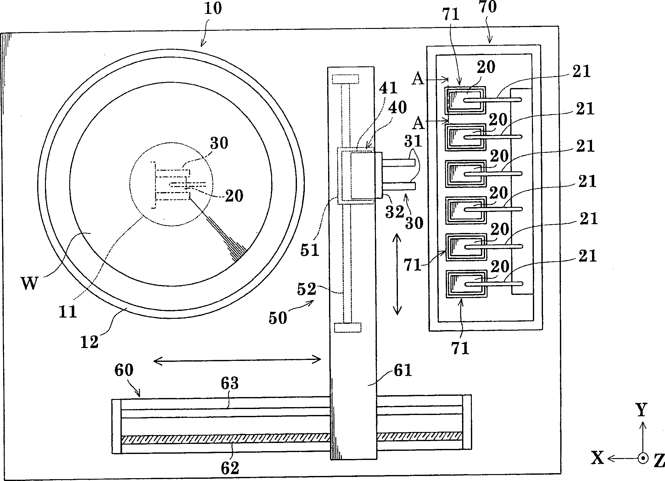
[0068] image 3 is a plan view showing the outline of the spin coating apparatus of the chemical processing apparatus in the first embodiment of the present invention. Figure 4 A side view of the device.
[0069] In the first embodiment, description will be made taking a spin coating device as an example of a chemical processing device. The spin coating apparatus performs an anti-corrosion treatment of a wafer by supplying an anti-corrosion agent solution as a treatment solution onto a semiconductor wafer (hereinafter simply referred to as "wafer").
[0070] Such as image 3 As shown, the spin coating device includes: a spin processing station 10, which is used to spin coat the supplied processing solution to the wafer W; a nozzle clamp 30, which is used to hold and transport the processing solution. A nozzle 20; a vertical moving device 40, which is used to move the nozzle clamp 30 vertically (along the Z-axis direction); a Y-axis horizontal moving device 50, which is use...
no. 2 example
[0106] Below, will refer to Figure 10 A second embodiment is described. Figure 10 is a plan view showing the outline of a spin coating apparatus which is a chemical processing apparatus according to a second embodiment of the present invention.
[0107] In the first embodiment described above, the backup station 70 includes six storage tanks 71 each having the temperature control tank 80 and the backup tank 90 arranged in two vertical stages. In the second embodiment, the backup station 70 includes only six backup tanks 90 , and a single temperature control tank 80 is provided independently of the backup tanks 90 . The same parts as in the first embodiment are denoted by the same reference numerals, and will not be specifically described.
[0108] A feature of the spin coating apparatus in the second embodiment is that a single temperature control tank 80 is provided independently of six spare tanks 90 .
[0109] Next, the operation of the spin coating apparatus in the se...
no. 3 example
[0113] refer to Figure 11 to Figure 13 A third embodiment will be described. Figure 11 is a plan view of an outline of a spin coating device of a chemical processing device in a third embodiment of the present invention. Figure 12 is a plan view showing the outline of the clamp arm temperature control unit 97 . Figure 13 is a plan view showing the outline of a nozzle holder 30 .
[0114] In the above-mentioned second embodiment, the spare station 70 includes six spare tanks 90 , and a single temperature control tank 80 is provided independently of the spare tanks 90 . The nozzle clamp 30 clamps the clamping portion 27 of each nozzle 20 . In the third embodiment, such as Figure 11 As shown, a clamping arm temperature control unit for controlling the clamping arm 31 of the nozzle clamp 30 is provided independently of the temperature control tank 80 . Such as Figure 13 As shown, the clamping arm 31 of the nozzle clamp 30 clamps the heat exchange portion (the front pla...
PUM
 Abstract
Description
Claims
Application Information
 - R&D Engineer
- R&D Manager
- IP Professional
- Industry Leading Data Capabilities
- Powerful AI technology
- Patent DNA Extraction
Browse by: Latest US Patents, China's latest patents, Technical Efficacy Thesaurus, Application Domain, Technology Topic.
© 2024 PatSnap. All rights reserved.Legal|Privacy policy|Modern Slavery Act Transparency Statement|Sitemap