Electromagnetic driving apparatus for controlling weft-guide in loom
An electromagnetic drive, loom technology, applied in looms, current controllers, auxiliary equipment for weaving, etc., can solve problems such as cost increase, and achieve the effect of improving motion response
- Summary
- Abstract
- Description
- Claims
- Application Information
AI Technical Summary
Problems solved by technology
Method used
Image

Examples
no. 1 example
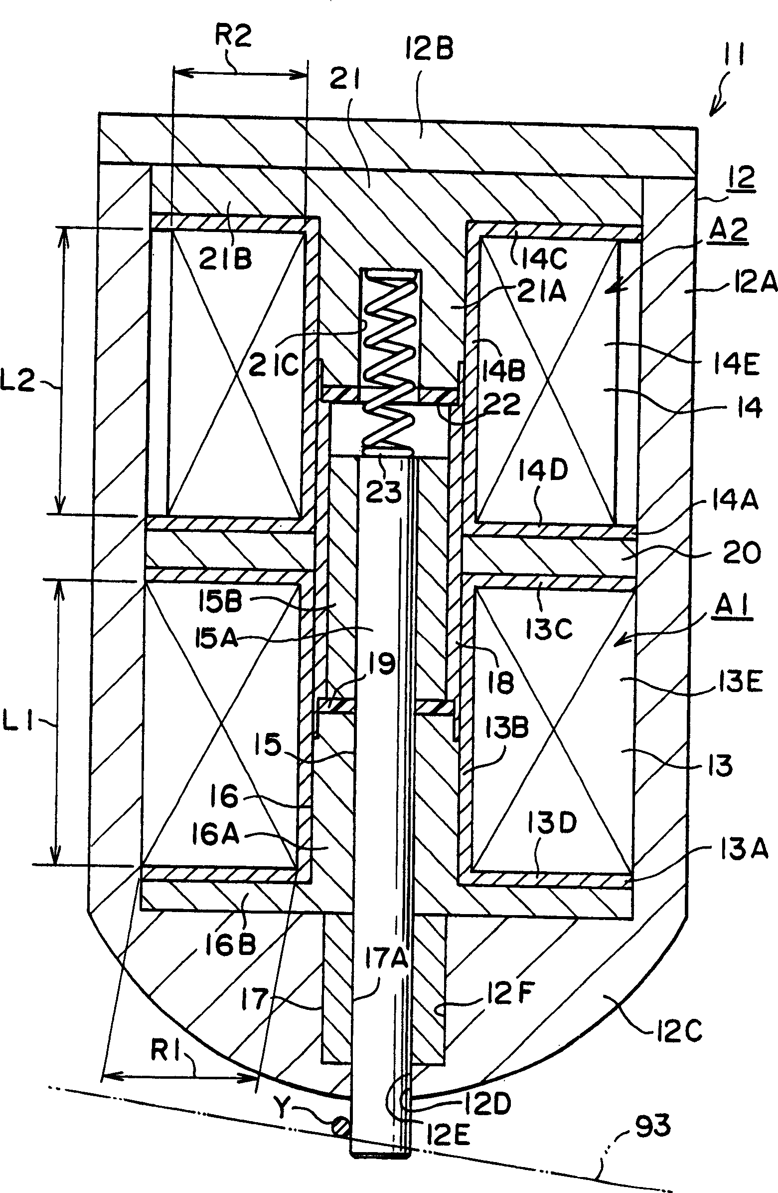
[0034] will now refer to figure 1 A first embodiment of the present invention will be described.
[0035] Such as figure 1 As shown, the electromagnetic driving device (hereinafter referred to as "electromagnetic driving device") 11 for controlling weft insertion includes a housing 12, and the electromagnetic driving device includes a stop electromagnetic coil 13, a release electromagnetic coil 14, and a movable element 15. The housing 12 is composed of a main housing 12A formed substantially as a bottomed cylinder and a disc-shaped cover portion 12B fixed to an opening on the upper side of the main housing 12A, as as seen in the picture. The bottom 12C of the main housing 12A forms a substantially hemispherical structure.
[0036] At the center of the bottom 12C, a hole 12D is formed which vertically penetrates the bottom 12C as seen in the drawing. The hole 12D is composed of a small inner diameter portion 12E formed at the lower portion of the hole and a large inner ...
no. 2 example
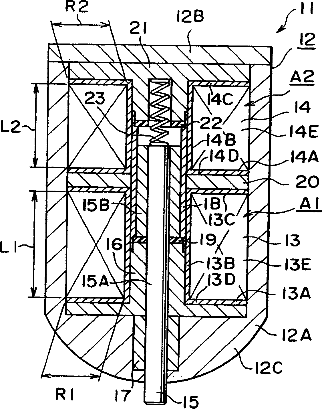
[0062] The second embodiment is mainly realized by changing the configuration of the release electromagnetic coil 14 in the first embodiment. In other words, it has the same configuration as the first embodiment. Therefore, the same elements as those of the first embodiment are denoted by the same reference numerals, and descriptions of these elements are omitted.
[0063] As in the first embodiment, in Figure 2A In the shown electromagnetic drive device 11 , the number of turns of the release electromagnetic coil 14 is set to be less than the number of turns of the stop electromagnetic coil 13 . In this embodiment, the axial length of the coil frame 14A of the release electromagnetic coil 14 is set to be smaller than the axial length of the coil frame 13A of the stop electromagnetic coil 13 . That is, in this embodiment, the axial length of the release coil winding area A2 is smaller than the axial length of the blocking coil winding area A1.
[0064] In this embodiment, ...
no. 3 example
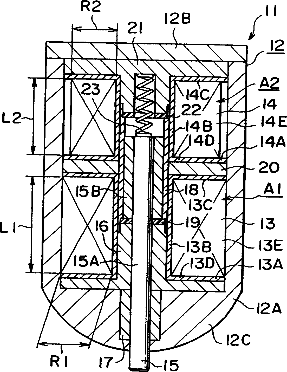
[0068] The third embodiment is achieved by changing the configuration of the release electromagnetic coil 14 in the second embodiment. In other words, it has the same configuration as the first embodiment. Therefore, the same elements as those in the second embodiment are denoted by the same reference numerals, and descriptions of these elements will be omitted.
[0069] exist Figure 2B In the electromagnetic driving device 11 shown, the number of turns of the release electromagnetic coil 14 is set to be less than that of the second embodiment. That is, in this embodiment, the releasing coil width R2 is smaller than the blocking coil width R1, and the releasing coil height L2 is smaller than the blocking coil height L1. The coil wire diameter d2 is set equal to the coil wire diameter d1.
[0070] This embodiment provides the same advantages as the above-mentioned advantages (1), (2), and (3).
PUM
 Abstract
Description
Claims
Application Information
 - R&D
- Intellectual Property
- Life Sciences
- Materials
- Tech Scout
- Unparalleled Data Quality
- Higher Quality Content
- 60% Fewer Hallucinations
Browse by: Latest US Patents, China's latest patents, Technical Efficacy Thesaurus, Application Domain, Technology Topic, Popular Technical Reports.
© 2025 PatSnap. All rights reserved.Legal|Privacy policy|Modern Slavery Act Transparency Statement|Sitemap|About US| Contact US: help@patsnap.com