Equilized demodulation method used in mobile communication system

A mobile communication system and balanced demodulation technology, applied in the field of mobile communication systems, can solve the problems of increased complexity, large amount of calculation, and many resources, and achieve the effects of improving receiving performance, fast execution speed, and small computational complexity

Inactive Publication Date: 2003-09-17
ZTE CORP
2 Cites 11 Cited by

AI-Extracted Technical Summary

Problems solved by technology

However, due to the use of blind equalization technology, the complexity of its calculation is greatly increased
[0010] Since the Viterbi algorithm needs to be used for iterative processing when performing balanced demodulation of the data sent by the wireless channel, the amount of calcu...

Method used

Method of the present invention has comprehensively considered performance, complexity, stability and convergence rate of balanced demodulation method, has adopted improved Viterbi algorithm to input baseband digital I, Q signal is carried out balanced demodulation, solves mobile Various distortions of the signal in the wireless channel dur...

Abstract

An equilibrium demodulation method used in the mobile communication system includes: carrying on amplitude limitation process for them after sampling data of I (phase inversion) and Q (quadrature) ofbaseband are received by the mobile terminal and further carrying on rotation removel treatment and converting the received multiple data to real number, utilizing the training series kept the storage to carry on related calculation for estimating impact response of channel, conforming the position for the training serial in input series, calculating the mensuration initial value, and then carrying on iteration calculation for obtaining state transfer diagram and utilizing the state transfer diagram to obtain decoding output series.

Application Domain

Technology Topic

Phase inversionDemodulation +3

Image

  • Equilized demodulation method used in mobile communication system
  • Equilized demodulation method used in mobile communication system
  • Equilized demodulation method used in mobile communication system

Examples

  • Experimental program(1)

Example Embodiment

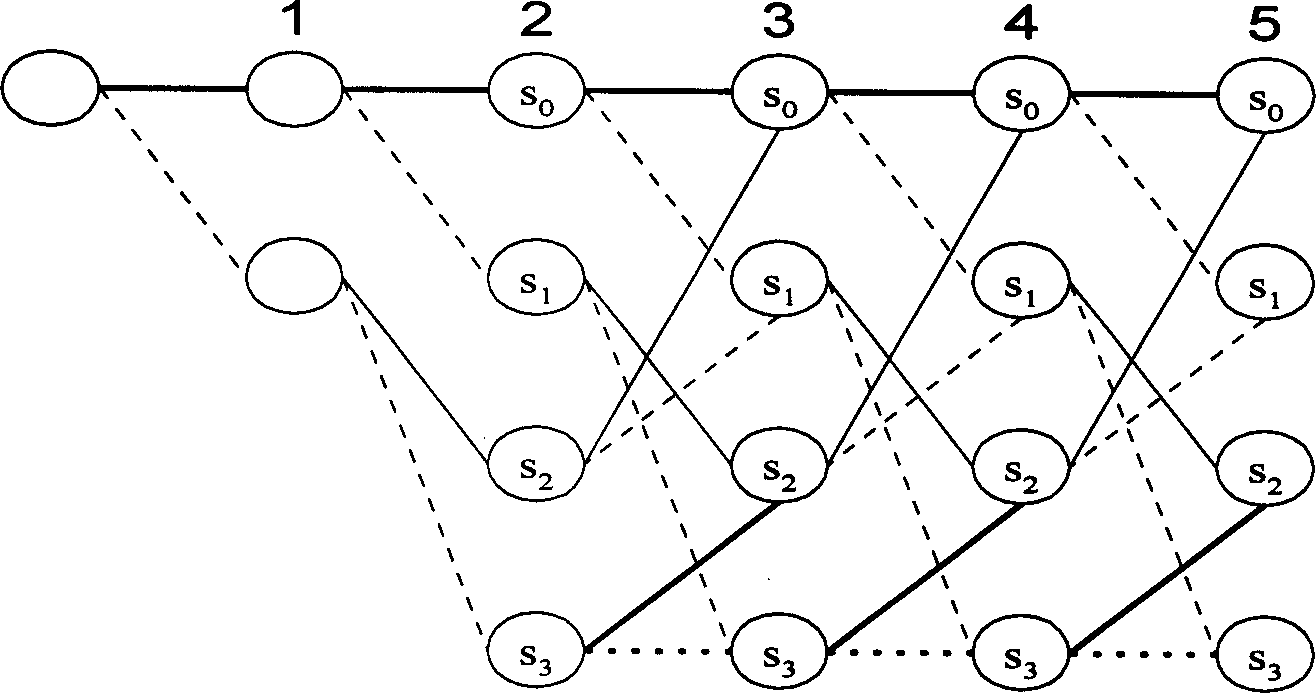
[0027] The method of the present invention comprehensively considers the performance, complexity, stability and convergence speed of the balanced demodulation method, adopts the improved Viterbi algorithm to carry out balanced demodulation to the input baseband digital I, Q signal, and solves the problem of signal in mobile communication. Various distortions in the wireless channel, such as the zero point of the channel characteristics, especially the intersymbol interference caused by the multipath effect.
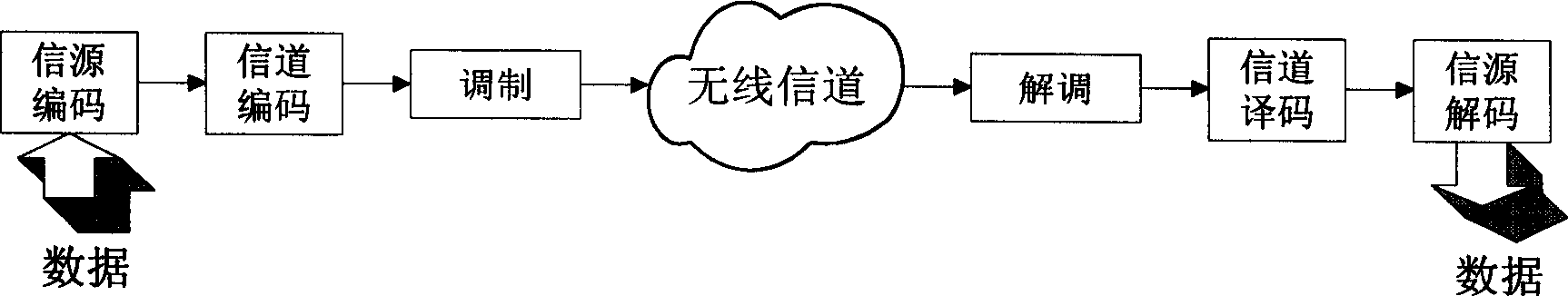
[0028] figure 1 It is a schematic diagram of the channel model of the mobile communication system. The mobile terminal receives the data sent through the wireless channel. The demodulation module demodulates the received baseband I and Q signals first, and then sends the demodulated results to the channel The decoding module performs channel decoding. For the control channel, the information sent by the system can be directly obtained so far; for the business channel, the voice or data sent by the system still needs to be decoded. Due to the influence of multipath fading and Doppler frequency shift, the mobile wireless channel is extremely variable, so it is necessary to introduce equalization technology during demodulation to improve the quality of the receiving channel.
[0029] figure 2 is a grid diagram formed by a discrete-time inter-symbol interference model, where the kth information symbol d k After being sent, the state of the "encoder" at time k is s k ,s k =(d k , d k-1 ,...,d k-L+1 ). figure 2 Among them, sequence length N=5, symbol set size M=2, channel dispersion length L=2, and there are L+M time units (nodes) in total. Each state in the trellis diagram has M output branches. For a certain time unit i, if the branch leaving each state is a solid line, the information bit input to the "encoder" at the next moment (i+1) is d i+1 = 1; if the branch leaving each state is a dotted line, the information bit input to the "encoder" at the next moment (i+1) is d i+1 =0. Each path in the grid graph corresponds to an input information sequence, and a maximum likelihood path can be obtained by using the metric formula, and the maximum likelihood estimation of the input sequence can be obtained.
[0030] Just because the intersymbol interference does not destroy the one-to-one correspondence between the input and output sequences, the intersymbol interference of the signal after passing through the wireless channel can be regarded as a convolutional encoder. The decoding algorithm of convolutional code can be used for signal detection in intersymbol interference channel after modification, so Viterbi algorithm—maximum likelihood algorithm can be used for channel equalization to solve intersymbol interference and demodulation.
[0031] image 3 It is the existing basic MLSE equalizer. Since the Viterbi algorithm needs to maintain independence between consecutive samples, the noise must be whitened and filtered. A noise whitening filter needs to be added to the equalizer, and the noise whitening filter and the matched filter can be combined into a whitening matched filter. Therefore the MLSE equalizer includes a whitening matched filter, a channel estimation module, a training sequence and an equalization module.
[0032] The equalization module will be described in detail below from the perspective of minimum error probability. Suppose the equivalent signal received by the receiver is r ( t ) = Σ k d k h ( t - kT ) + n ( t ) - - - ( 1 ) where {d k} is the transmitted information symbol sequence, h(t) is the impulse response of the baseband system, n(t) is zero-mean additive Gaussian noise; the autocorrelation function of n(t) is w(τ)=2N 0 k(τ), when n(t) is white noise, k(τ)=δ(τ), T is the symbol period.
[0033] For n(t) is white noise (noise variance is 2N 0 ), derive the joint probability density of the received signal vectors. Suppose the received random information bit sequence vector Dg =[d 1 , d 2 ,...,d g ], the received random signal is rev N =[r 1 , r 2 ,...,r N ], where g≤N, then the joint probability density is p ( rev N D g ) = ( 1 2 πN 0 ) N exp ( - 1 2 N 0 Σ k = 1 N | r k - Σ m d m h km | 2 ) - - - - ( 2 ) Among them, h km is the baseband impulse response.
[0034] Obviously, the amount of calculation to solve the maximum value of formula (2) is too large, so the logarithm of formula (2) can be taken, and the number N of observed data tends to infinity, then the value of formula (2) is proportional to MM ( D g ) = - ∫ - ∞ + ∞ | r ( t ) - Σ k d k h ( t - kT ) | 2 dt - - - - ( 3 ) = - ∫ - ∞ + ∞ | r ( t ) | 2 dt + 2 Re Σ k d k * ∫ - ∞ + ∞ r ( t ) h * ( t - kT ) dt ] - Σ u Σ v d u * d v ∫ - ∞ + ∞ h * ( t - uT ) h ( t - vT ) dt - - - - ( 4 ) In the above formula, Re means to take the real part of the complex number, and * means the conjugate of the complex number (the same below).
[0035] For symbolic vector D g The maximum likelihood estimation of can be obtained by satisfying MM(D g ) of the maximum value of D g to get. make: z k = z ( kT ) = ∫ - ∞ ∞ r ( t ) h * ( t - kT ) dt - - - - ( 5 ) Then formula (4) becomes J i ( { d k } ) = Σ k 2 Re ( a k * Z k ) - Σ i Σ k a i * S i - k a k - - - - ( 6 ) where J i ({d k}) is the measure of the kth symbol. and S l = S ( lT ) = ∫ - ∞ + ∞ h * ( t ) h ( t + lT ) dt - - - - ( 7 ) Suppose the length of the sending sequence is N, and the sending sequence is D g , when the channel time dispersion length is finite, that is, there is an integer such that |l|>L, S l = 0, and S l = S - l * , sequence D g The measure of can be recursively calculated by formula (8): J N ( . . . , d N - 1 , d N ) = J N - 1 ( . . . , d N - 1 ) + Re [ d N * ( 2 Z n - S 0 d N - 2 Σ I = 1 l S l d N - l ) - - - - ( 8 )
[0036] For a sequence of N symbols {d n}, where each symbol is selected from the set of M-ary symbols, so there is M N kind of combination. If N is very large, it will take a huge amount of computation to use the exhaustive method to find the metric, and it is more appropriate to use the Viterbi algorithm to find the metric.
[0037] Viterbi Algorithm - Maximum Likelihood Estimation Algorithm is aimed at the grid graph ( figure 2 ) to search for a path with the maximum metric, and then get the maximum likelihood estimation of the input sequence after demodulation.
[0038] Figure 4 is a schematic diagram of the MVA MLSE equalizer constructed according to the method of the present invention, and image 3 Compared with it, it increases the limiter, inverter, and its matched filter ratio image 3 The matched filter in is simply ( image 3 The matched filter in also contains the whitening matched filter). Compared with the basic MLSE equalizer, this equalizer has two advantages: 1. It does not need a whitening matched filter, and only needs to perform matched filtering on the input; 2. It does not need a square operation in the measurement calculation, but only needs to use a simple multiplication operation.
[0039] The limiter (401) performs limit processing on the input baseband I and Q signals, and limits the signals between ±64. In a specific embodiment of the present invention, fixed-point DSP is adopted to realize the balanced demodulation method described in the present invention, and the value range of numerical values ​​in the fixed-point DSP is limited, when realizing " adding-comparing-selecting " measurement update, The saved new measurement value is very likely to exceed the representation range of DSP, that is, overflow, which will not only cause incorrect decoding, but even cause the system to crash. Also need to consider when adopting DSP to realize: 1) Can adapt to larger dynamic range; 2) Guarantee overflow does not occur in the operation process. Therefore, before using the input data for iterative calculation, it needs to undergo a series of processing to ensure that no overflow occurs during the iterative process.
[0040] The inverter (402) performs inversion processing on the input baseband I and Q signals. After the baseband signal is reversed, it can be considered that what is transmitted on the channel is a sequence of real symbols {d n}, at this time the channel parameter is {g i}. due to {d n} is a sequence of real numbers, so it is more convenient to calculate the measure of the sequence.
[0041] Matched filter (403) is to realize with transversal filter, and the tap interval of transversal filter is T p , the number of taps is N p +1,T p with N p should meet N p T p ≥LT, f M is the highest frequency of the signal r(t), and LT is the bandwidth of the channel impulse response h(t). For GMSK signal, f M = 100KHz, so T p ≤5μs can meet the requirements. To make the problem simpler, the tap interval of the transversal filter can be taken as the bit period T, so that the signal r(t) sent to the equalizer does not have to be an analog signal, but can be at a rate f s = f b The digital signal obtained by sampling the baseband signal, where f s , f b represent the sampling frequency and symbol rate respectively, so the transversal filter can be realized with a digital filter. Since r(t) is a complex signal, sampling r(t) is at the rate f s = f b Simultaneously sample the I and Q signals at a rate f s = f b Sampling r(t), we can get: r k = r ( t ) | t = kT = Σ i d k - i j k - 1 h ( iT ) + n k - - - - ( 9 )
[0042] order b i = d i j i When , it can be considered that what is transmitted on the channel is a complex sequence {b n}, the channel parameter is {h i}. At this time, MLSE can be used to estimate the complex sequence {b n}, although b i ∈ {+1, -1, +j, -j}, but the number of states of MVA MLSE can still be considered as 2 L , instead of 4 L , then there are complex operations in the iteration of the metric. After the input signal passes through the inverter (403), the complex number sequence can be regarded as a real number sequence for operation.
[0043] The channel estimator (404) extracts the training signal (506) required by the training process from the memory for channel estimation. In this way, the process of channel estimation is actually a correlation operation process, and when the calculation of the cross-correlation function is completed, the estimation of the channel parameters is completed.
[0044] For the inverted signal, the signal waveform at the receiving end is: y ( t ) = Σ i d i ( t - iT ) - - - - ( 10 ) Among them, d i is the sent symbol, and g(t) is the response of the system after inversion. By finding y(t) and sequence {d i} cross-correlation, the channel response g(t) can also be obtained
[0045] After inversion processing, the response of the matched filter is: g MF (t)=g * (-t), here the noise is considered to be white noise, that is, the autocorrelation function of the noise is: 2N 0 δ(τ). When a transversal filter with a tap interval of T is used as a matched filter, the tap coefficient of the matched filter is: g MF ( i ) = g - i * = g * ( t ) | t = - iT i = L , . . . , 1 - - - - ( 11 ) where g MF (i) is the ith tap of the matched filter.
[0046] The MVA MLSE equalization module (405) gets S from the channel estimator l After that, the branch metric F(s k-1 ,s k ). After inversion processing, the symbol {d n} is a real sequence, so in finding F(s k-1 ,s k ), only use S l the real part of . In the periodic training mode, the channel estimator only works in the training phase. In the data transmission phase, it is assumed that the time variation of the channel is small, and the branch metric F(s k-1 ,s k ) is calculated in advance and made into a table, the amount of calculation of the equalizer in the digital transmission stage can be greatly reduced.
[0047] The sequence measurement iteration formula of the MVA MLSE equalization module (405) still adopts formula (8). At state k, the state of the "encoder" is denoted as s k =(d k , d k-1 ,...,d k-L+1 ), at time k, the output of the matched filter is Z k. Assuming that the length of the sequence to be estimated is set to N, the process of MVA MLSE is as follows:
[0048] 1) Starting from the time unit k=L, calculate the metric of each state corresponding to the sequence of L segment branches, state s L =(d L ,...,d 1 ) The corresponding partial surviving sequence is (d 1 , d 2 ,...,d L ), the metric of its sequence (path) is: J ~ L ( S L ) = Σ 2 Re ( d n * Z n ) - Σ i = 1 L Σ j = 1 L d i * S i - j d j - - - - ( 12 ) The surviving sequences and surviving sequence metrics corresponding to each state are stored.
[0049] 2) k is increased by 1, and the branch of this node entering each state is connected with the previous node connected by these branches, and M L+1 path. For each state, select and store a path with the largest metric from the M paths entering the state as a new surviving path, the largest metric is used as the surviving metric of the state, and delete all other non-surviving paths. The total number of surviving paths is still M L strip. status k The calculation formulas of the survival metric and the path corresponding to the survival metric are as follows: J k ( S k ) = 2 Re ( a k * Z k ) + max { S k - 1 } → S k { J ~ k - 1 ( S k - 1 - F ( S k - 1 , S k ) } - - - - ( 13 )
[0050] In the above formula, {s k-1} for s k The set of predecessor states of the state, F(s k-1 ,s k ) by s of k-1 nodes k-1 state to k-node s k Branching metrics for states: F ( s k - 1 , s k ) = d k * S 0 d k + 2 Re ( d k * Σ l = 1 L S l d k - l ) - - - - ( 14 ) k-nodes k The surviving sequence of states is [u k-1 , d k ], u k-1 is the state s that makes formula (10) obtain the maximum value k-1 The corresponding surviving sequence, d k for state s k The first symbol of , s k =(d k , d k-1 ,...,d k-L+1 ).
[0051] 3) If k
[0052] When the channel changes with time, an adaptive method can be adopted, and the matched filter gMF(t) and the channel parameter {Sl} are all adjusted adaptively.
[0053] Add channel estimator (404), training sequence (406), limiter (401), inverter (402) to maximum likelihood sequence estimation MVA MLSE module (505), and adopt horizontal matched filter (403) , the MVAMLSE equalizer can be obtained, that is, Figure 4 shown.
[0054] The balanced demodulation method utilizes the improved Viterbi algorithm, which is realized by fixed-point DSP software programming, and its algorithm complexity is small.
[0055] The calculation of the metric in the MVA MLSE module (405) utilizes the grid graph, and the transfer of the grid graph has certain rules. Taking one of the states, there are two states before it that can be transferred to it, such as Figure 5 As shown, m ∈ [0, 7], a total of 16 states.
[0056] The segmented calculation method is adopted in the measurement calculation, and only 2×n (n is the number of states) paths of the transition are calculated each time, and then the process of "adding, comparing, and selecting" is carried out. If the k state is the leading state, there are n paths and the metric values ​​of the n paths at this time. When transferring from the k state to the k+1 state, the total path increases to 2×n, and the metric values ​​are the first n The metric value of the path is added to the metric of the corresponding 2×n transition paths. It can be seen from the state diagram that each k+1 state has two leading states, that is, there are two transfer paths to reach the state, compare the metric values ​​of these two paths, and select one of the larger metric values ​​to keep. And keep its metric value, and discard the path and metric with the smaller metric. If two paths have the same metric, choose one. In this way, there are still n paths and n metrics in the k+1 state, and then the next transition is calculated until the end. After the end, find the path with the largest metric value, and the state transition process on the grid diagram is the desired sequence.
[0057] When performing decoding output, you can not generate a sequence during calculation, just remember which state each state is transferred from, so that when the calculation is completed, you only need to find the point with the largest metric value in the last n states, and record The transferred result is pushed back to the beginning, and the output sequence is obtained. This method occupies less storage capacity and has a slightly faster operation speed.
[0058] The GSM standard stipulates that the length of time dispersion that can resist channel multipath during demodulation is 16 μs, which is equivalent to a little more than 4 bits of burst pulse. If 5 bits are used, the number of states of the MVA MLSE is 32, which is relatively complicated. To reduce the computational complexity, 16-state MVA MLSE can be used, which can resist intersymbol interference within 4 symbols, and the channel time delay spread that can resist is about 14.8μs. The output of the MVA MLSE equalizer is a maximum likelihood estimation sequence of the transmitted sequence.
[0059] After simulation and actual verification, the method fully meets the requirements of the GSM specification (the demodulation time of a burst is less than the duration of a burst in GSM, 569us). Adopt this method in the mobile communication system, especially the balanced demodulation method designed and implemented in the GSM/GPRS system, which compensates the intersymbol interference caused by the multipath effect, and has fast execution speed, small computational complexity, and balanced demodulation effect Well, the consumption of hardware resources is less, and the receiving performance of the receiver in the mobile communication system is improved.

PUM

no PUM

Description & Claims & Application Information

We can also present the details of the Description, Claims and Application information to help users get a comprehensive understanding of the technical details of the patent, such as background art, summary of invention, brief description of drawings, description of embodiments, and other original content. On the other hand, users can also determine the specific scope of protection of the technology through the list of claims; as well as understand the changes in the life cycle of the technology with the presentation of the patent timeline. Login to view more.

Similar technology patents

Interrupt handling method and device

ActiveCN101976206AFast executionReduced probability of interrupt lossProgram initiation/switchingOperating systemComputer science
Owner:北京中星天视科技有限公司

Method and system for BitMap Analysis System for high speed testing of memories

InactiveUS20060248414A1Low area overheadFast executionStatic storageEqual sizeTester device
Owner:STMICROELECTRONICS PVT LTD

Classification and recommendation of technical efficacy words

Why Eureka
Try Eureka