
Picture recording system, image data source device and picture recording device

A technology for image recording and image data, applied in printing devices, image communication, digital output to printing units, etc., can solve problems such as insufficient printing speed of engine units, difficult matrix recording methods, increased load of image processing units, etc.

Inactive Publication Date: 2003-10-01
CANON KK
View PDF0 Cites 0 Cited by
  • Summary
  • Abstract
  • Description
  • Claims
  • Application Information

AI Technical Summary

Problems solved by technology

[0016] In the processing of the control unit of the PD printer system, as in the case of the Non-PC system, it is not possible to expect a significant increase in cost to have sufficient memory and a high-speed CPU like a PC. The processing of the printer driver is used as it is, and the image quality and speed cannot be maintained
In fact, in the PD printer system that has been commercialized now, there are few products that can make full use of the printing speed in the engine unit of the printer due to the processing load in the controller unit.
[0017] In addition, regarding these problems, even in the case of using the matrix recording method described in the prior art, it is necessary to pre-embed PD-specific specifications in the engine unit of the basic printer, which is very important for the basic printer alone. Redundant specifications, which may cause problems such as storage units that may affect the program
[0018] In particular, when the basic printer has been commercialized, in the PD printer with the control unit added as an accessory, the processing speed of the control unit cannot be reached at the data resolution that the printer can receive, and the engine unit cannot be fully satisfied. print speed problem
[0019] That is to say, it is expected that the problems in the system for image output from devices other than PCs that are more popular in the future to the printer are roughly as follows: (1) If the processing of the printer driver performed on the PC is used as it is, the image processing unit The load increases, and the image quality and speed cannot be maintained (including the overall speed of image processing speed, data transmission speed, and printing speed)
(2) In order to adopt the matrix recording method to solve the above problem (1), there are various working environments, and it is difficult to include all suitable matrix recording methods in the printer engine

Method used


Image

  • Picture recording system, image data source device and picture recording device
  • Picture recording system, image data source device and picture recording device
  • Picture recording system, image data source device and picture recording device

Examples


Embodiment approach 1

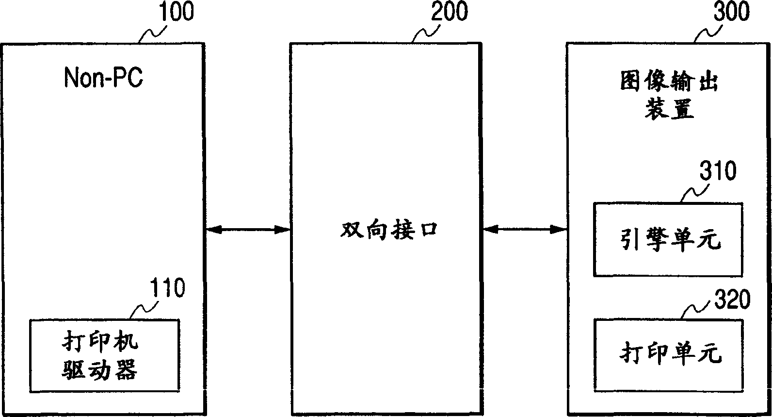
[0041] First, refer to figure 1 The configuration of the information processing system according to Embodiment 1 of the present invention will be described. figure 1 It is a block diagram showing the configuration of the information processing system of the first embodiment. The information processing system includes a non-PC 100, a bidirectional interface 200, an image output device 300 constituted by a printer, and the like. The non-PC 100 and the image output device 300 are connected via the bidirectional interface 200 . The non-PC 100 is, for example, an apparatus that does not use a PC such as WebTV (registered trademark) and SetTopBox, and the printer driver 110 is installed in the memory of the non-PC 100 . In addition, the image output device (printer) 300 includes an engine unit 310 that performs image processing and a printing unit 320 that performs printing on a recording medium.

[0042] Refer below Figure 2 to Figure 5 A method of generating print data in t...

Embodiment approach 2

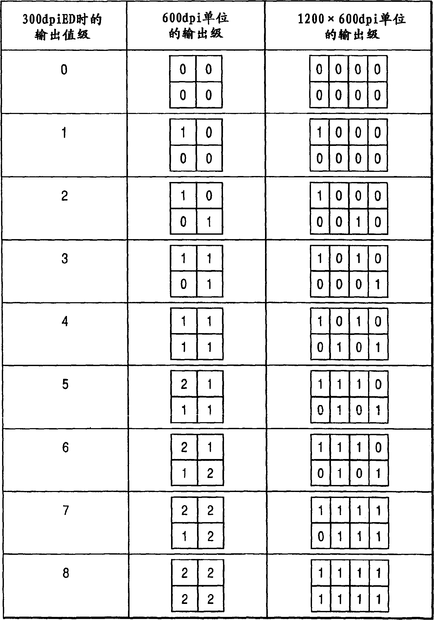
[0063] In Embodiment 1 of the present invention described above, the quantization resolution in the printer driver, the transfer resolution from the printer driver to the engine unit of the printer, and the printing resolution are the same for each color (common for each color). On the other hand, in Embodiment 2 of the present invention, the quantization resolution in the printer driver, the transfer resolution from the printer driver to the engine unit of the printer, and the printing resolution are described as being different for each color. In the engine unit of the printer according to Embodiment 2, 5-value data of 600 dpi is received for CM (cyan, red), expanded to 4 pixels of 1200 dpi for binary recording, and 600 dpi is received for YK (yellow, black). The binary data is recorded in binary at 1 pixel of 600dpi as it is.

[0064] Next, refer to Figure 6 to Figure 11 A photo direct (PD) printing apparatus according to Embodiment 2 will be described. FIG. 6 is a persp...

Embodiment approach 3

[0094] In Embodiment 1 and Embodiment 2 of the present invention described above, the data output form to the printer engine and the development of the recording data in the printer engine are described in the case of using the known matrix recording method. In contrast, in Embodiment 3 of the present invention, other methods will be described. In Embodiment 3, it is assumed that the printer engine provided as a printer accepts multi-valued data of 600 dpi, and ejects 0 to n' segments corresponding to the multi-valued data of 0 to n' for the same pixel of 600 dpi. In the case of a printer engine that forms images with a plurality of ink droplets and in the case of a machine that sends multi-value data of 600dpi as a host PC. In such a printer engine, the number of steps 0 to n' of the average unit pixel transferred to the engine unit may not necessarily coincide with the actual number of ink droplets ejected to the unit pixel. For example, for the input data to the four-value...


PUM


Abstract

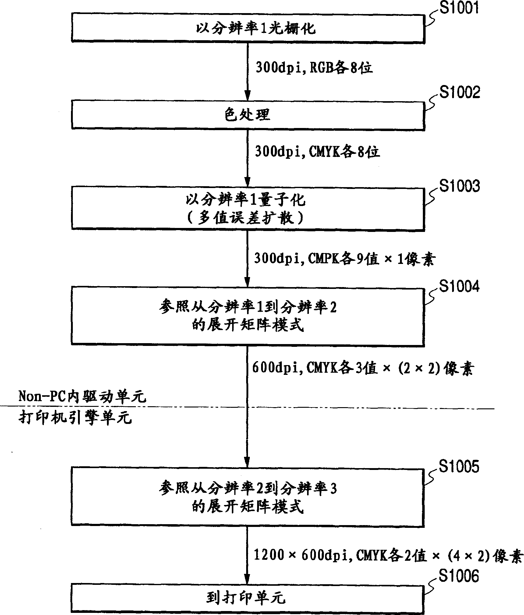
An image recording system, an image data source device and an image recording device are provided. Among them, the Non-PC printer driver controls the quantization of image data at the quantization resolution (resolution 1), and converts the quantization data quantized at the quantization resolution to the data resolution (resolution 2). Control and control of transferring the data converted into the data resolution to the engine unit of the image output device, and the engine unit of the image output device converts the data of the transferred data resolution into the recording resolution of the recording medium (resolution 3 ) to control, and at the same time, make the quantization resolution lower than the data resolution value. Thereby, even in an environment without a sufficiently large memory or a high-speed CPU, it is possible to provide image output maintaining image quality and speed, and to flexibly respond to various environments.

Description

technical field [0001] The present invention relates to an image recording system, an image data source device, and an image recording device that expand image data into recording data corresponding to a predetermined dot array, and use a matrix mode process for recording an image on a recording medium with a plurality of recording elements. . An image processing method and program. More specifically, it relates to an image recording system capable of providing high-quality images at high speed, an image data source device, an image recording device, an image processing method, and a program. Background technique [0002] Currently, in recording devices that record images on recording media such as paper, there is an effort to increase the resolution of image data in order to increase the image quality. However, if the image data becomes high resolution, the amount of data to be processed is large, and there is, for example, a host computer (host, host PC) that transmits the...

Claims


Application Information

Patent Timeline
Patent Type & Authority Applications(China)
IPC IPC(8): B41J5/30B41J2/525G06F3/12H04N1/41H04N1/46H04N1/60H04N1/64
CPCH04N1/648B41J2/01
Inventor 加藤真夫渡辺知行山田顕季
Owner CANON KK
Learn More