Method and device for controlling electromagnet in self-protection D.C. circuit

A technology of DC circuit and electronic control device, applied in the direction of electromagnet with armature, valve operation/release device, circuit, etc., can solve the problems of limiting the economic benefit of downhole production equipment and reducing the current, etc.

Inactive Publication Date: 2003-10-01
CATERPILLAR INC
View PDF4 Cites 5 Cited by
  • Summary
  • Abstract
  • Description
  • Claims
  • Application Information

AI Technical Summary

Problems solved by technology

[0005] In summary, the methods and devices used hitherto for controlling electromagnets of electrohydraulic valves have the disadvantage that they operate with a fixed current reduction that is dependent on the supply voltage
The techniques used to date to reduce the clamping current limit the economics that can be achieved with downhole production equipment

Method used


Image

  • Method and device for controlling electromagnet in self-protection D.C. circuit
  • Method and device for controlling electromagnet in self-protection D.C. circuit
  • Method and device for controlling electromagnet in self-protection D.C. circuit

Examples


Embodiment Construction

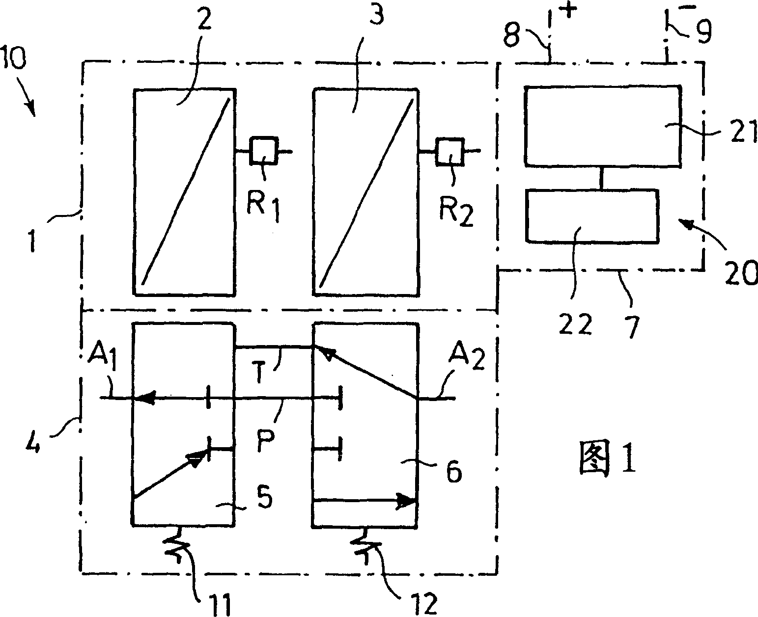
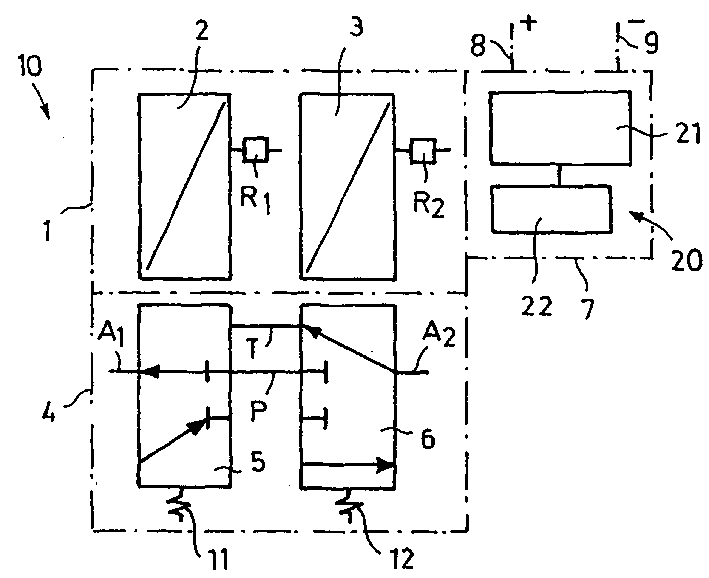
[0017] The electrohydraulic control valve, marked as a whole by 10 in FIG. 1, is of modular construction and comprises an electromagnet housing 1 made of ferromagnetic material and containing two electromagnets 2, 3, which, as is known, The two electromagnets each have an armature, not shown, which can be moved back and forth between a starting position and a switching position by applying current to an associated coil, also not shown. A valve module 4 is connected to the electromagnet housing 1 with a flange, which includes two multi-way hydraulic valves 5, 6, which can be opened and closed independently of each other by means of the electromagnets 2, 3. Here the hydraulic valve 5 shown in FIG. 1 is in the switch position, with the customer connection terminal A1 connected to the high voltage line P, and the hydraulic valve 6 is shown in the departure position, with the customer connection terminal A2 connected to the return line T. The electrohydraulic valve 10 also includes...


PUM


Abstract

The invention relates to a method for controlling an electromagnet connected in a self-protected DC circuit, which can be controlled to switch back and forth between two switching positions, and is used to actuate a locking object of a hydraulic valve, wherein by means of an electronic control device in the The coil of the electromagnet is fed with an excitation current under the suction state of the electromagnet armature, and a holding current smaller than the excitation current is fed to the coil of the electromagnet under the holding state of the armature. The present invention also relates to A device used to achieve a reduction in the holding current. According to the invention, the actual current in the coil is continuously measured after the electromagnet is controlled, and this current is evaluated for the movement of the armature. The method of the present invention is based on the one hand that the force of the electromagnetic movable part is proportional to the current flowing, and on the other hand that the movement of the movable part causes a reverse inductance in the magnetic coil, which reduces the measured actual current value in the coil. The movement of the armature is detected immediately at the beginning of the movement or shortly thereafter, so that energy regulation can be carried out in an optimal manner, preferably by reducing the current to the clamping current value by means of pulse width modulation.

Description

Technical field: [0001] The invention relates to a method for controlling an electromagnet connected in a self-protected direct current circuit, which can be switched back and forth between two switching positions in a controlled manner, for actuating a hydraulic valve's blocking object, wherein by means of an electronic control In the device, the coil of the electromagnet is fed with an exciting current when the armature of the electromagnet is in the pulling state, and is fed with a holding current that is smaller than the exciting current in the holding state of the armature. The invention also relates to a device for controlling an electromagnet connected in a self-protected direct current circuit, switchable to and fro between two switch positions, for operating a hydraulic valve locking object, the device comprising a coil And the electromagnet of the armature, and also includes the electronic control device, by means of the electronic control device, the current fed can...

Claims


Application Information

Patent Timeline
Patent Type & Authority Applications(China)
IPC IPC(8): H01F7/18
CPCH01F7/1805H01F7/1844
Inventor 赫尔姆特·海曼吉斯·狄斯切特汉斯-尤度·莱纳
Owner CATERPILLAR INC
Why Eureka
Try Eureka