
Vehicle drive controlling apparatus and method

A vehicle and controller technology, applied in the control device, transmission device, engine control and other directions, can solve the problems of engine braking force change, shock, fuel efficiency deterioration, etc., and achieve the effect of suppressing shock

Inactive Publication Date: 2003-11-05
TOYOTA JIDOSHA KK
View PDF0 Cites 35 Cited by
  • Summary
  • Abstract
  • Description
  • Claims
  • Application Information

AI Technical Summary

Problems solved by technology

As a result, fuel supply restarts, deteriorating fuel efficiency
Conversely, if the engagement torque is set to a high value, the engine braking force changes sharply, which may produce a shock

Method used


Image

  • Vehicle drive controlling apparatus and method
  • Vehicle drive controlling apparatus and method
  • Vehicle drive controlling apparatus and method

Examples


Embodiment

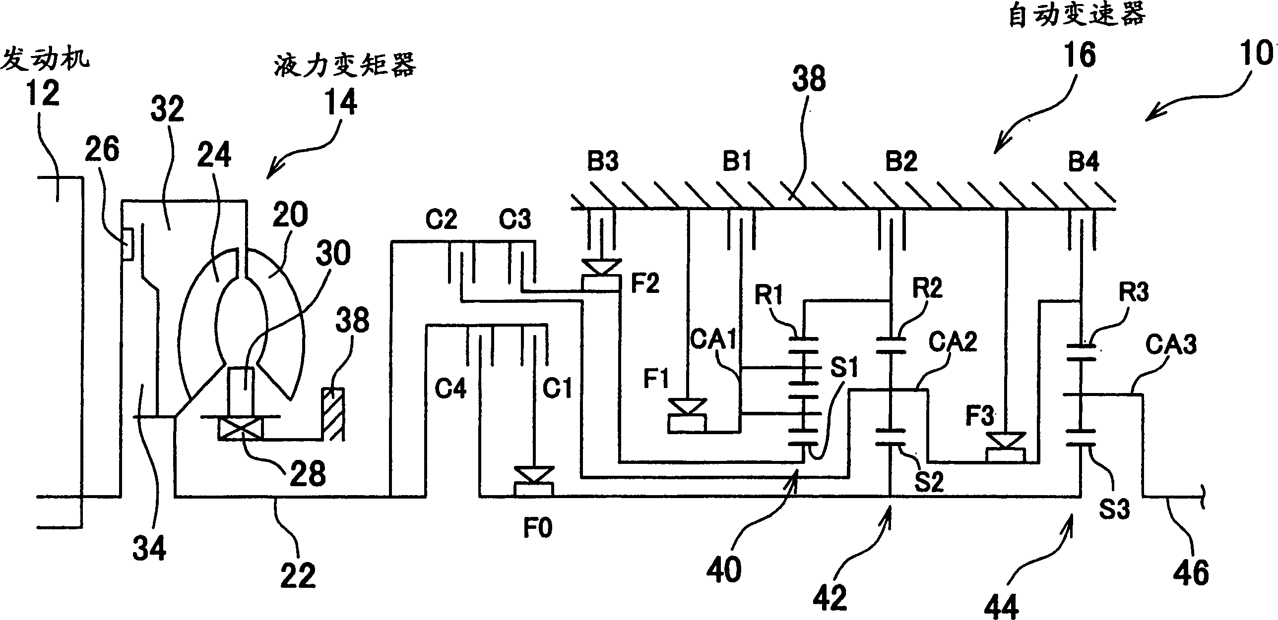
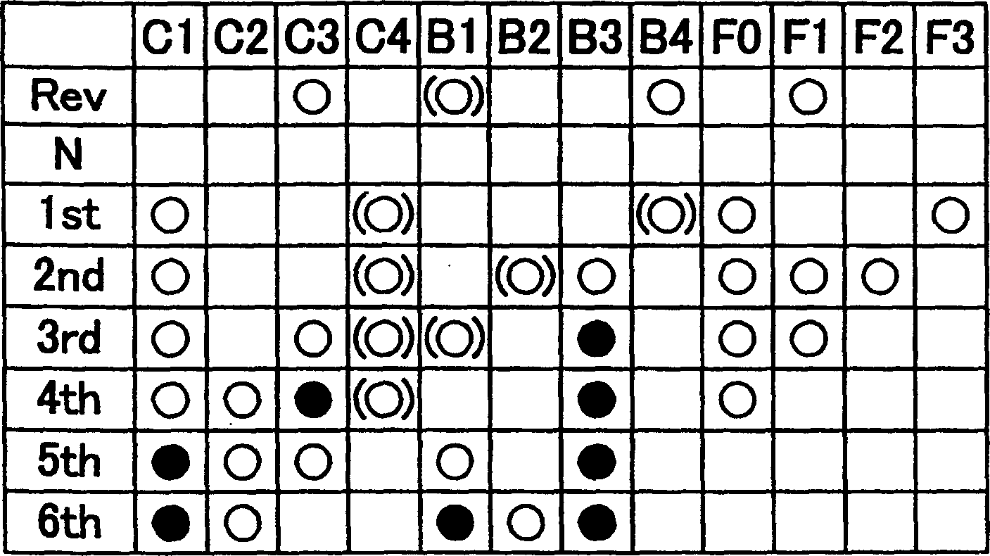
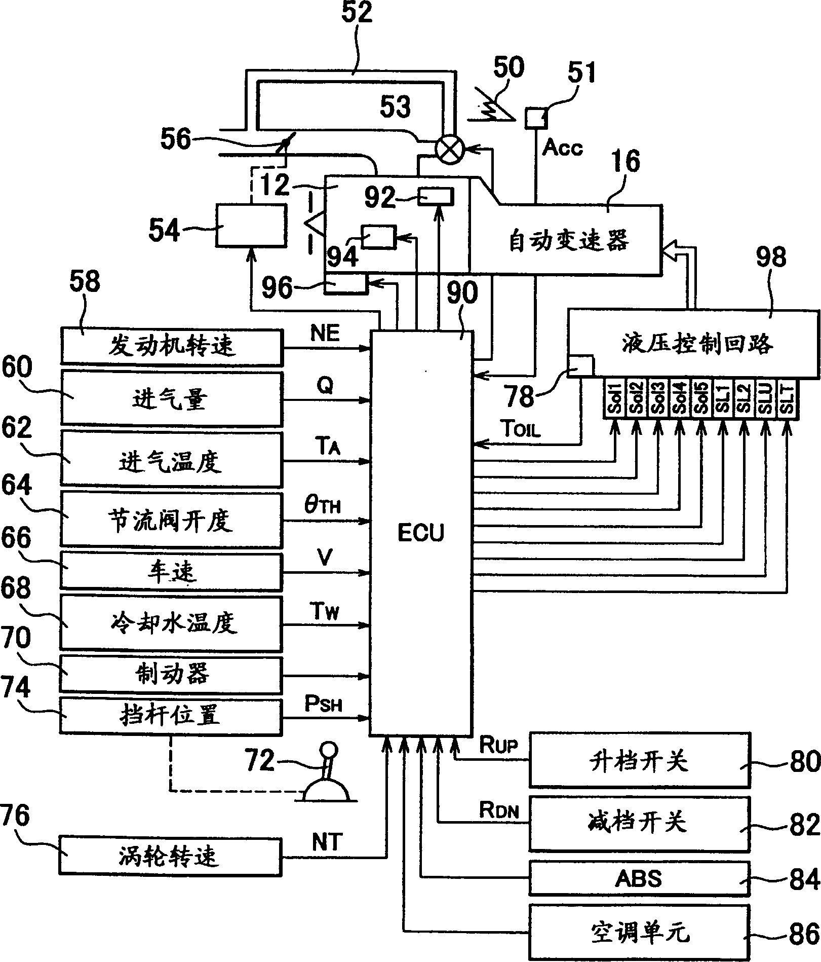
[0062] An embodiment of the present invention will be described with reference to the drawings. figure 1 It is a structural schematic diagram of a vehicle driving device 10 to which the present invention has been applied. Refer to attached figure 1 , the output of an internal combustion engine 12 as a driving power source is sent to an automatic transmission 16 through a torque converter 14 as a fluid type power transmission device to be transmitted to drive wheels through an axle. The torque converter 14 includes a pump vane 20 connected to the engine 12, a turbine vane 24 connected to the input shaft 22 of the automatic transmission 16, a stator vane 30 whose rotation in one direction is restrained by a one-way clutch 28 , and a lock-up clutch 26 that transmits power through the fluid between the pump blade 20 and the turbine blade 24 so as to be directly connected. The lock-up clutch 26 is a hydraulic friction clutch which is frictionally engaged by a pressure difference ...


PUM


Abstract

A vehicle drive control device comprising an engine 12 that generates power by combustion of fuel; an automatic transmission 10 that transmits a reverse input from a drive wheel to the engine and operates between multiple forward gears each having a different gear ratio. A fluid power transmission device 14 provided between the automatic transmission and the engine for transmitting power by fluid, the power transmission device having a lock-up clutch; and a controller 90 . The controller executes the fuel cut control 104 for stopping fuel supply to the engine when the fuel cut condition including when the vehicle is in a coasting state when the throttle valve of the engine is fully closed and the engine speed is equal to or greater than a predetermined value is established; Control 120 for engaging the lock-up clutch is performed when a lock-up clutch engagement condition including the vehicle is in a coasting state is established; at a coasting vehicle speed that varies according to the state of the lock-up clutch under the control for engaging the lock-up clutch Next, the downshift control 114 of the automatic transmission is executed.

Description

technical field [0001] The present invention relates to a vehicle drive control device, and more particularly, to a vehicle drive control performed in a coasting state of a vehicle when a throttle valve is fully closed. Background technique [0002] A known vehicle drive control device includes (a) an engine for generating power through fuel combustion, (b) a fluid power transmission device having a lock-up clutch for transmitting power through a fluid, (c) an engine for A unit that executes a fuel cut control that stops fuel supply when a fuel cut condition is established, the fuel cut condition including when the throttle valve of the engine is fully closed and the vehicle is in a coasting state, and the engine speed is equal to or greater than one that is restored during the fuel cut operation (hereinafter referred to as F / C recovery engine speed), and (d) a unit for engaging a lock-up clutch when a lock-up clutch engagement condition is established including that the veh...

Claims


Application Information

Patent Timeline
Patent Type & Authority Applications(China)
IPC IPC(8): B60W10/04B60W10/00B60W10/02B60W10/06B60W10/10B60W30/18F02D9/02F02D29/00F02D41/00F02D41/12F02D41/32F16H59/18F16H59/24F16H59/44F16H59/46F16H59/50F16H59/68F16H61/02F16H61/04F16H61/14F16H61/21F16H63/50
CPCB60W10/06B60W10/115B60W30/18B60W30/19B60W2510/0638F02D41/0005F02D41/123F02D41/187F02D2011/102F02D2200/0404F02D2200/0414F02D2200/602F16H61/0213F16H61/04F16H61/143F16H61/21F16H2059/186F16H2059/467F16H2061/0234F02D41/023F16H2061/147F16H2061/0496B60W10/04B60W10/10B60W30/1819Y02T10/60F16H61/14
Inventor 松原亨友松秀夫田中义和能森文人
Owner TOYOTA JIDOSHA KK
Learn More