

Jet fuel producing process
A technology for jet fuel and heavy raw materials, applied in the petroleum industry, hydrotreating process, processing hydrocarbon oil, etc., can solve the problem that the hydro-upgrading operation unit cannot operate independently, and achieve the effect of expanding the source of raw materials
- Summary
- Abstract
- Description
- Claims
- Application Information
AI Technical Summary
Problems solved by technology
Method used
Image

Examples
Embodiment 1
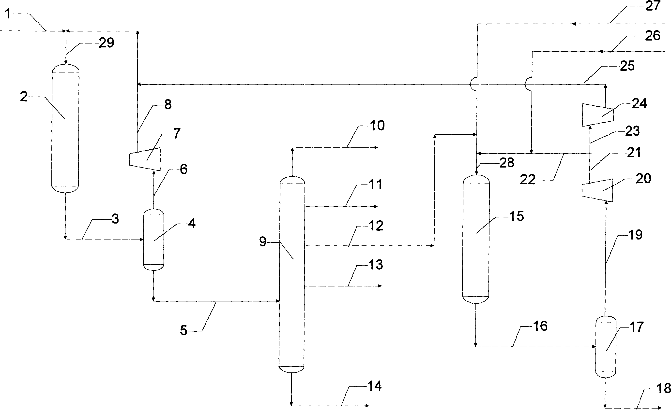
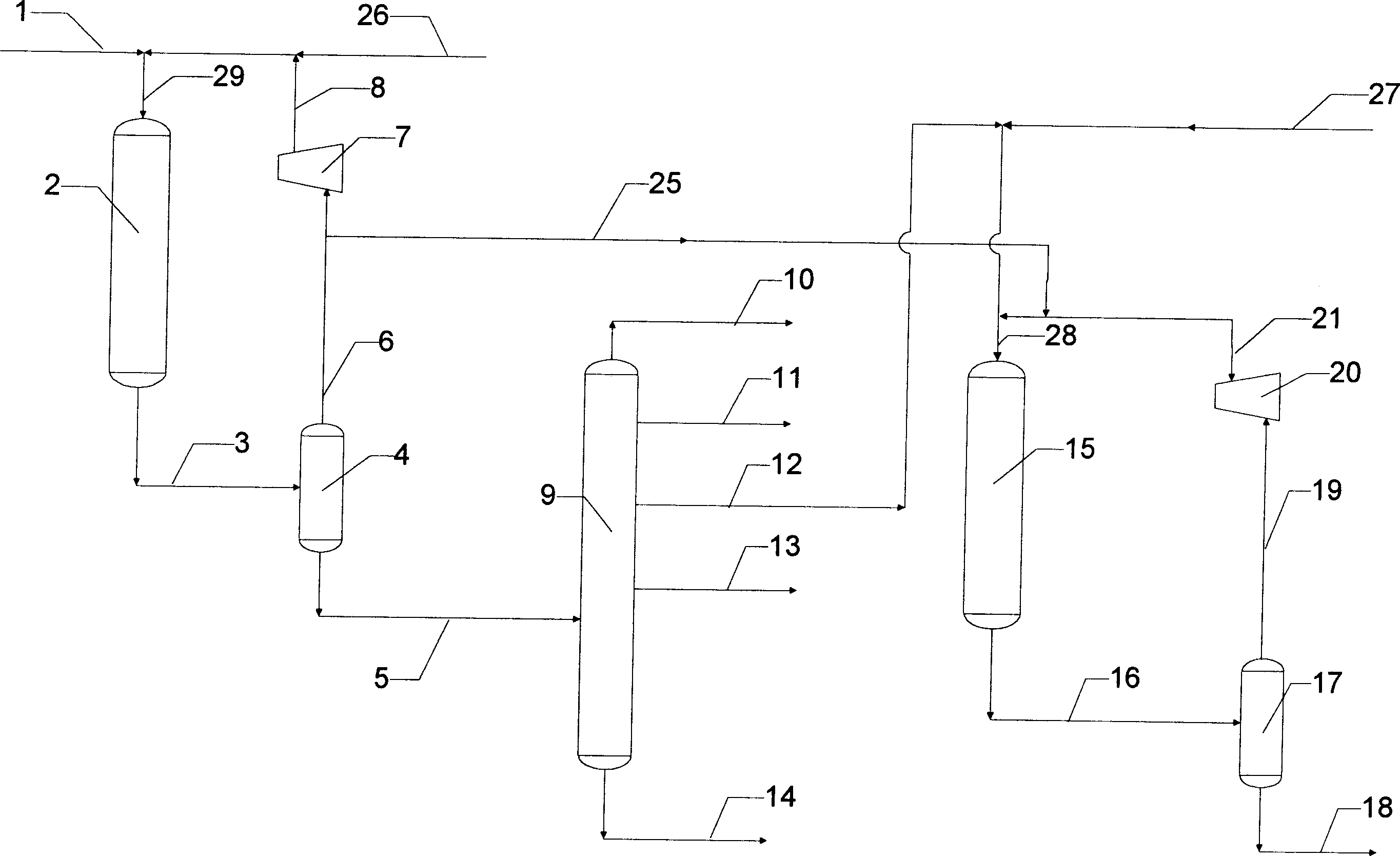
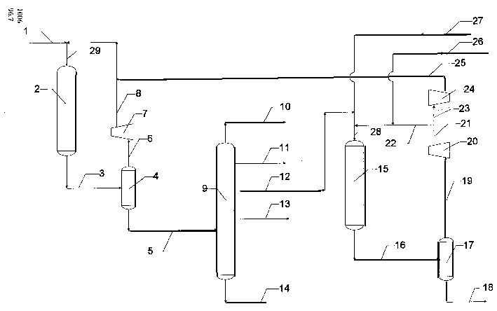
[0043] Vacuum gas oil A and hydrogen enter the hydrocracking reactor, pass through the catalysts RN-2 and RT-5 in sequence, at a hydrogen partial pressure of 10.0MPa, a temperature of 375 / 372°C (refining / cracking), and a space velocity of 1.0 / 1.0hr -1 (refining / cracking), hydrogen oil ratio 800Nm 3 / m 3 Reaction under the condition of separation reaction effluent to obtain light naphtha fraction, heavy naphtha fraction, kerosene fraction, diesel oil fraction, unconverted tail oil, wherein kerosene fraction and straight-run kerosene fraction A are mixed according to the mass percentage of 50:50 , enter the hydrotreating reactor together with hydrogen, and contact with catalyst RIC-1, at hydrogen partial pressure of 6.0MPa, temperature of 345°C, and space velocity of 1.5hr -1 , Hydrogen oil ratio 500Nm 3 / m 3 Under the condition of reaction, the reaction effluent is separated to obtain jet fuel fraction. The properties of vacuum gas oil A and straight-run kerosene A raw mate...
Embodiment 2
[0045] Vacuum gas oil B and hydrogen enter the hydrocracking reactor, pass through the catalysts RN-2 and RT-5 in sequence, at a hydrogen partial pressure of 8.0MPa, a temperature of 370 / 375°C (refining / cracking), and a space velocity of 1.5 / 1.8hr -1 (refining / cracking), hydrogen oil ratio 700Nm 3 / m 3Reaction under the conditions, separation of the reaction effluent to obtain light naphtha fraction, heavy naphtha fraction, kerosene fraction, diesel fraction, unconverted tail oil, wherein the kerosene fraction and straight-run kerosene fraction B are mixed in a mass percentage of 70:30 , enter the hydrotreating reactor together with hydrogen, and contact with the catalyst RIC-1, at a hydrogen partial pressure of 4.0MPa, a temperature of 335°C, and a space velocity of 3.0hr -1 , Hydrogen oil ratio 400Nm 3 / m 3 Under the condition of reaction, the reaction effluent is separated to obtain jet fuel fraction. The properties of vacuum gas oil B and straight-run kerosene B raw ma...
Embodiment 3
[0047] Vacuum gas oil C and hydrogen enter the hydrocracking reactor, pass through the catalysts RN-2 and RT-5 in sequence, at a hydrogen partial pressure of 8.0MPa, a temperature of 370 / 375°C (refining / cracking), and a space velocity of 1.5 / 1.8hr -1 (refining / cracking), hydrogen oil ratio 700Nm 3 / m 3 Reaction under the condition of separating the reaction effluent to obtain light naphtha fraction, heavy naphtha fraction, kerosene fraction, diesel oil fraction, unconverted tail oil, wherein the kerosene fraction and the straight-run kerosene fraction C are mixed according to the mass percentage of 70:30 , enter the hydrotreating reactor together with hydrogen, and contact with the catalyst RIC-1, at a hydrogen partial pressure of 4.0MPa, a temperature of 335°C, and a space velocity of 3.0hr -1 , Hydrogen oil ratio 400Nm 3 / m 3 Under the condition of reaction, the reaction effluent is separated to obtain jet fuel fraction. The raw material properties of vacuum gas oil C an...
PUM
 Abstract
Description
Claims
Application Information