Electron servo feed system

A feeding system and electronic technology, applied in feeding nozzles, glass manufacturing equipment, manufacturing tools, etc., can solve the problems affecting product quality and output, low product yield, poor control accuracy, etc., and achieve convenient and accurate operation. Punching, easy adjustment effect

Inactive Publication Date: 2003-12-03
SHANDONG SANJIN GLASS MASCH CO LTD
View PDF0 Cites 8 Cited by
  • Summary
  • Abstract
  • Description
  • Claims
  • Application Information

AI Technical Summary

Problems solved by technology

Difficult to adjust, complex operation, poor stability, poor control precision, low product yield, seriously affect product

Method used


Image

  • Electron servo feed system
  • Electron servo feed system
  • Electron servo feed system

Examples


Embodiment Construction

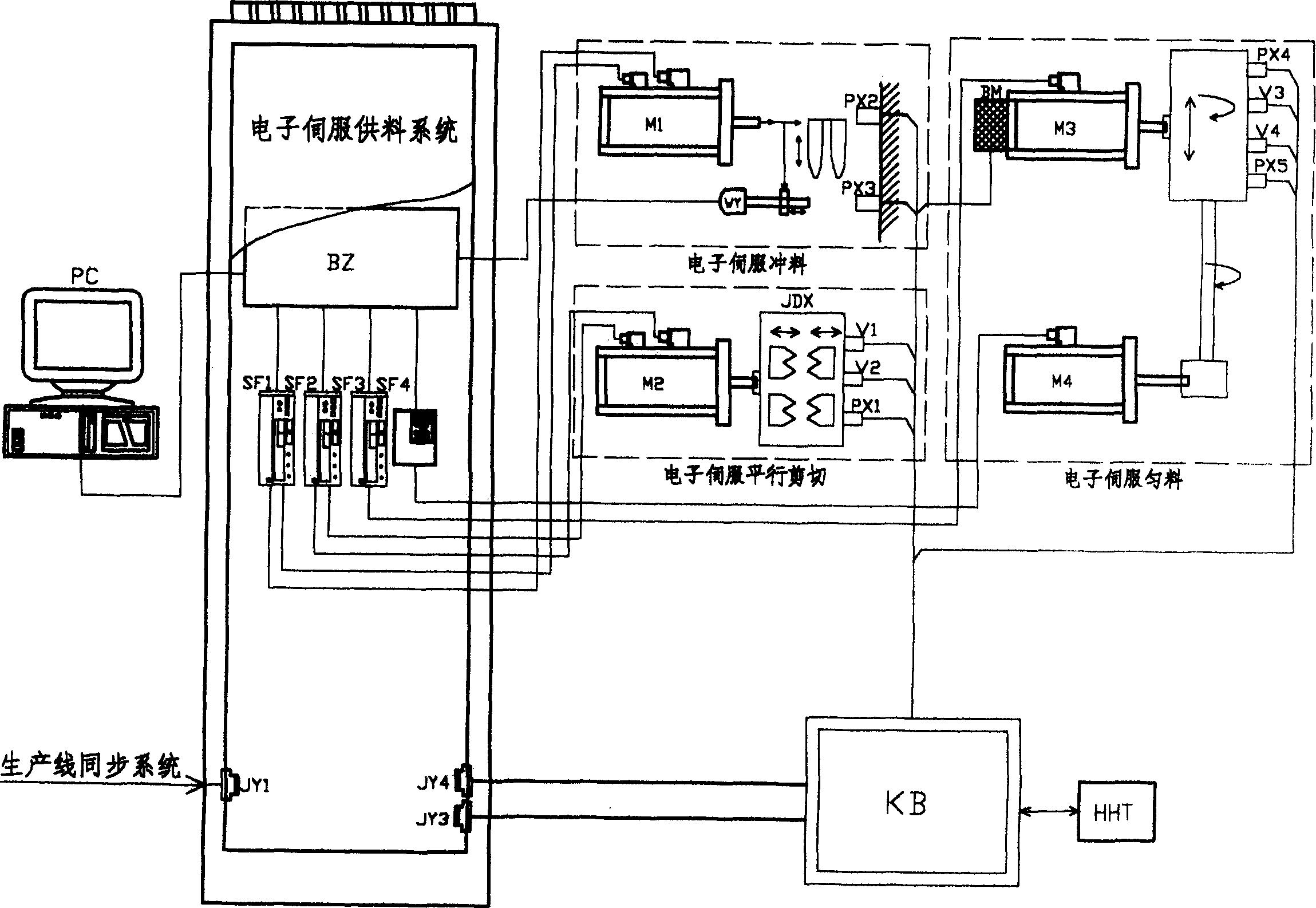
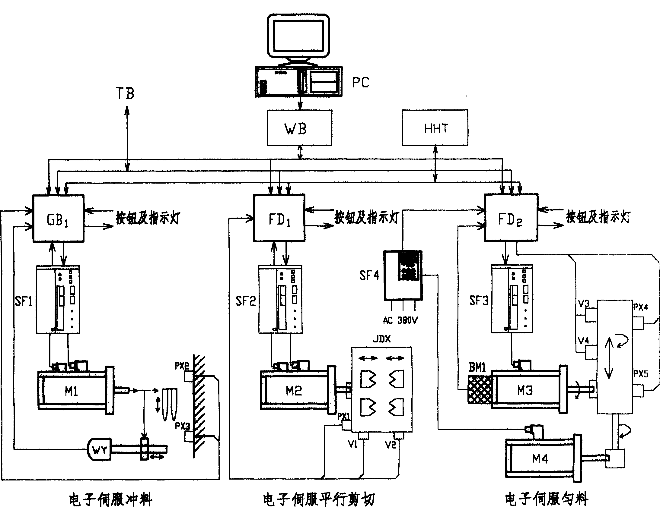
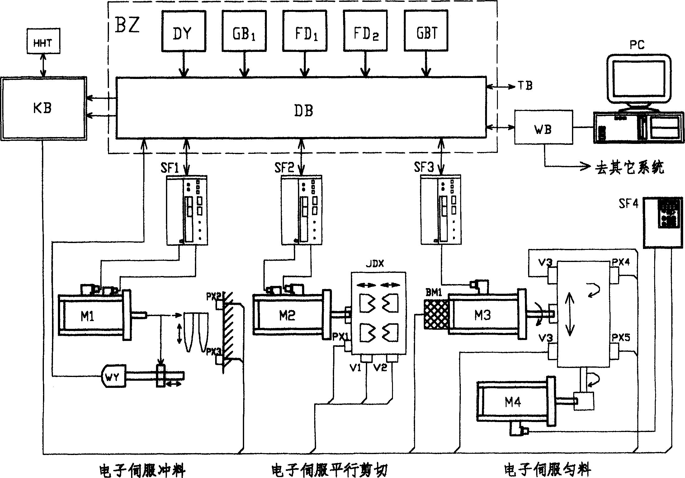
[0029] figure 1 Among them, the servo motor M1 driving the punch mechanism is connected to the punch microprocessor controller GB1 through the servo motor driver SF1 and the lower microprocessor controller unit BZ, the punch displacement sensor WY, the punch upper punch limit switch PX2, the punch The lower punch limit switch PX3 is installed on the punch device, and is connected with the microprocessor control unit GB1 of the punch mechanism through the microprocessor control unit BZ. Servo motor M1, under the control of punch mechanism microprocessor controller GB1 and servo driver SF1, drives the punch mechanism to perform punching operation according to the set electronic cam curve. If the punch exceeds the upper limit or At the lower limit position, the system first pulls the punch to the set position, alarms and stops.

[0030] The lower microprocessor controller GB1, the servo motor M1, the servo driver SF1, the punch mechanism and the displacement sensor WY driven by ...


PUM


Abstract

An electronic servo feeding system is composed of an electronic servo punching unit, an electronic servo parallel shearing unit, and an electronic servo homogenizing system. Under the action of computer, the intelligent control is applied to the electronic feeding system. Its advantages are simple structure, correct and reliable operations, and high rate of qualified products.

Description

technical field [0001] An electronic servo feeding system belongs to the field of glass machinery. Background technique [0002] The bottle making machine production line is composed of multiple divisions, which can be basically divided into feeding, distributing, bottle making, bottle pulling, bottle conveying, delivery, bottle pushing and other parts. The feeding system is one of the major divisions, and the feeding system is composed of punching, shearing and leveling. These three parts operate synchronously and coordinately, so that the cut gob can be shaped into a certain shape and provided to the bottle making machine, which finally makes bottles. The current customary feeding system is driven by a motor through the synchronous belt and gearbox to drive the mechanical cam of the punch and the mechanical cam of the scissors. The cam of the punch drives the punch to run through the linkage mechanism, and the cam of the scissors pushes the arm of the scissors to open and...

Claims


Application Information

Patent Timeline
IPC IPC(8): C03B7/00C03B7/08C03B7/10
CPCC03B7/10C03B7/005
Inventor 姜丰英
Owner SHANDONG SANJIN GLASS MASCH CO LTD
Why Eureka
Try Eureka