
Repairing method of carbon fiber surface defect

A carbon fiber and defect technology, which is applied in the field of surface cavity processing, can solve the problems of poor performance and the decline of carbon fiber mechanical performance indicators, etc.

Inactive Publication Date: 2003-12-17
陈新谋
View PDF0 Cites 22 Cited by
  • Summary
  • Abstract
  • Description
  • Claims
  • Application Information

AI Technical Summary

Problems solved by technology

The recovery of these surface holes has always been a matter of great concern in the field of carbon fiber production, but there is no good method so far, so at present, only the monofilament with existing holes can be sacrificed, resulting in a significant decline in the overall mechanical properties of carbon fibers

Method used


Image

  • Repairing method of carbon fiber surface defect
  • Repairing method of carbon fiber surface defect

Examples


Embodiment Construction

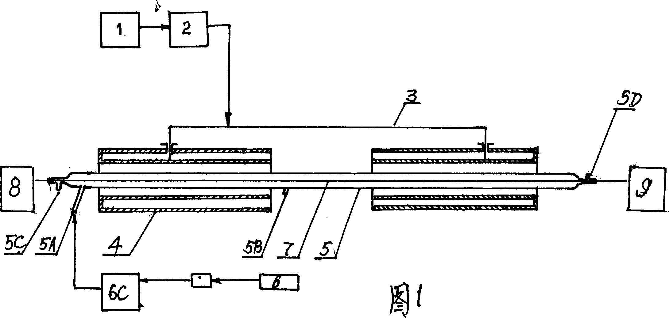
[0008] The carbon fiber 7 to be surface-treated passes through the quartz tube reactor 5 and is placed between the sending and receiving mechanisms 8 and 9, and the carbon fiber 7 is heated to between 110 and 1300°C under the induction of a strong focused electromagnetic field. The argon gas charged between , 5D ensures that external oxygen cannot enter the reactor 5, and the acetylene gas of 0.9 to 1.2 liters per hour enters the quartz reactor 5 from the gas filling port 5A against the direction of carbon fiber movement, and is combined with the carbon fiber at high temperature. The contact produces a cracking reaction, and the free carbon atoms generated by the reaction are deposited on the surface and cavity of the carbon fiber. The linear speed of the carbon fiber 7 in the quartz reactor is 2-3 m / min, which can effectively ensure the repairing purpose during the surface deposition of the carbon fiber 7 . The flow rate of argon filling at both ends is 0.5 liters / hour.

[0...


PUM


Abstract

A process for reparing the surface defects on the surface of carbon fibre by gas-phase deposition method includes such steps as preparing an acetylene reaction environment, putting the defective carbon fibres in it, heating by focused electromagnetic field to crack the acetylene into H2 and carbon atoms, and depositing the carbon atoms on the surface of carbon fibres.

Description

technical field [0001] The invention belongs to the improvement and supplement of the carbon fiber processing technology, especially the method for processing the surface cavity formed in the existing carbon fiber production technology. Background technique [0002] Carbon fiber (or graphite fiber) is processed and produced in the process of production, especially the carbon fiber processed and produced with polyacrylonitrile precursor as raw material. Due to the defects of the original filament itself and the uniformity of the processing process, the surface holes are formed. These holes cause the stress concentration phenomenon when the fiber is stressed, and are also the main factor for the breakage of the single filament. The recovery of these surface holes has always been a matter of great concern in the field of carbon fiber production, but there is no good method so far, so at present, only the monofilament with existing holes can be sacrificed, resulting in a signifi...

Claims


Application Information

Patent Timeline
IPC IPC(8): D01F9/22D01F11/16
Inventor 陈新谋
Owner 陈新谋
Learn More