

Digital control machine with magnetic suspension track girder
A technology of CNC machine tools and track beams, applied in the direction of motor vehicles, metal processing machinery parts, sliding/floating railway systems, etc., to achieve the effect of smooth control and high-precision positioning
- Summary
- Abstract
- Description
- Claims
- Application Information
AI Technical Summary
Problems solved by technology
Method used
Image

Examples
Embodiment Construction
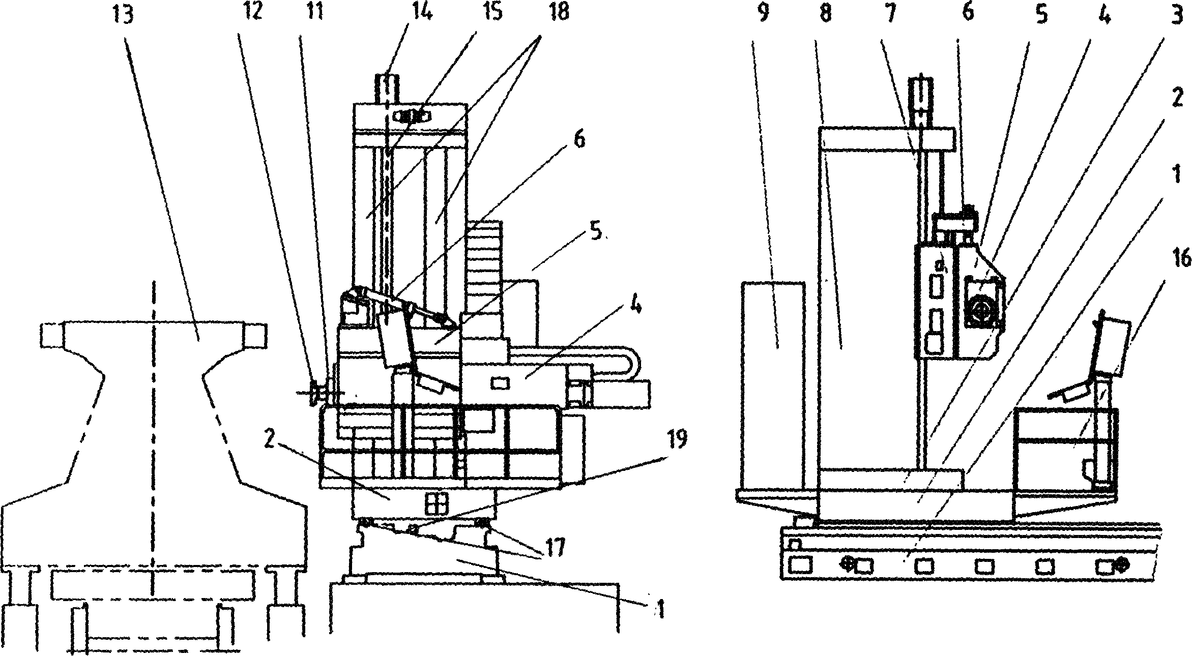
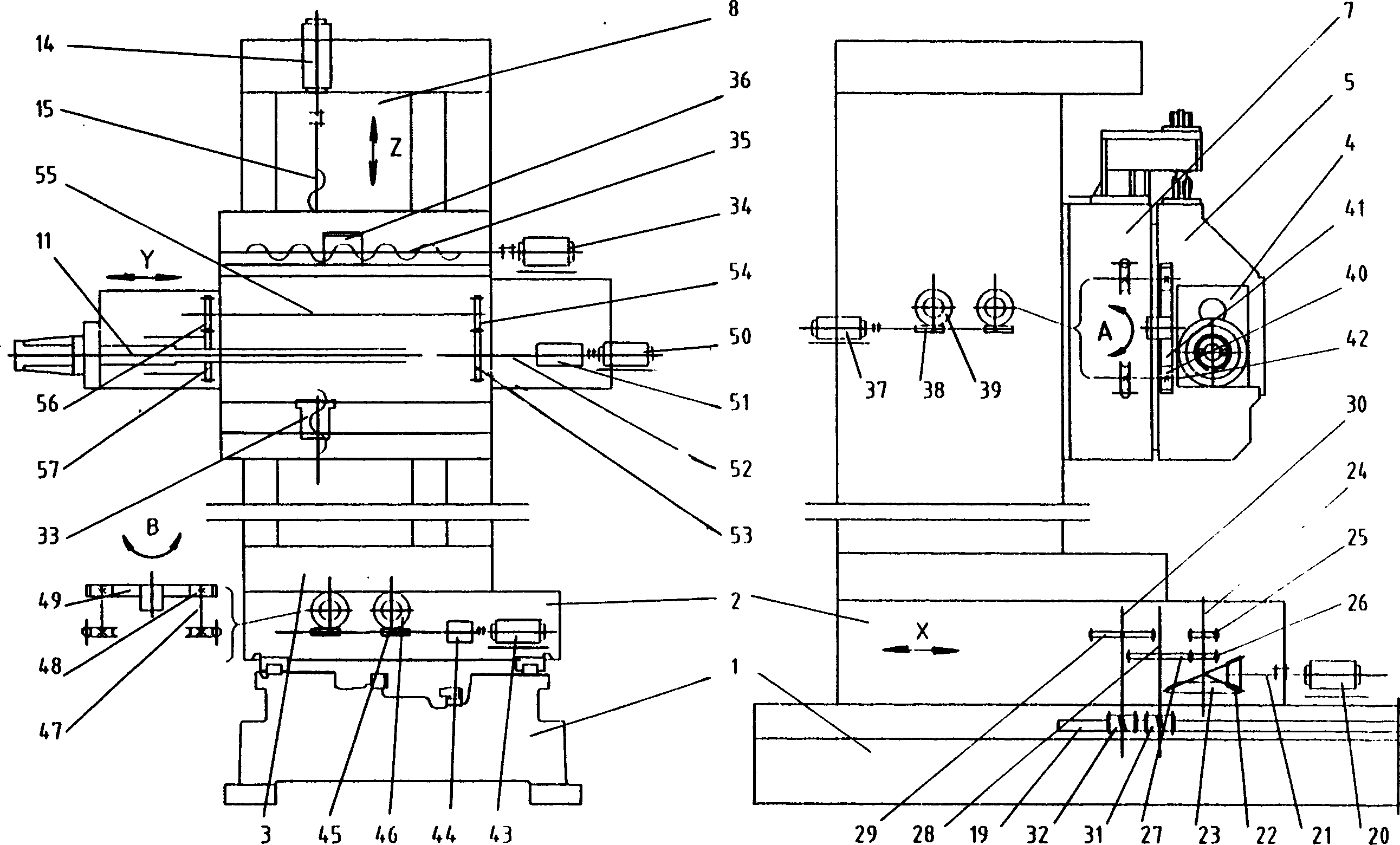
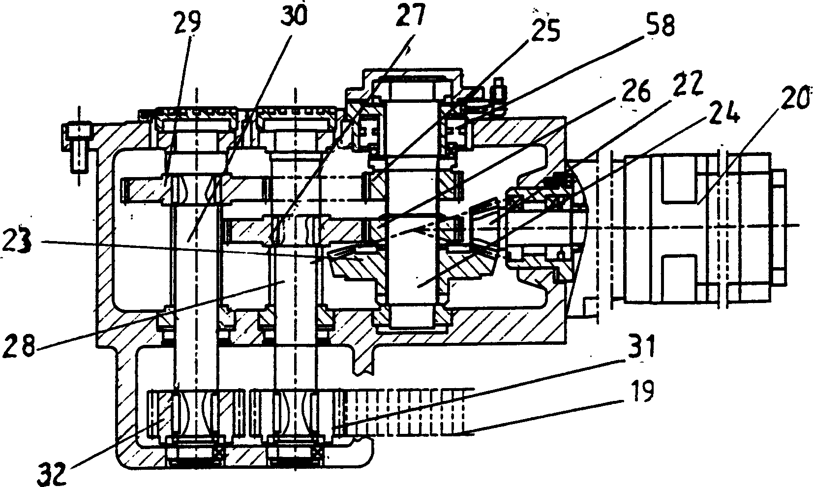
[0017] See first figure 1 . As can be seen from the figure, the magnetic suspension track beam CNC machine tool of the present invention includes a bed 1, a column 8, a spindle box 5, a ram 4, a main shaft 11, a control system 9, and an operation station 16. It is characterized in that the bed 1 is 36 meters long, The upper full length of the bed 1 is provided with two linear rolling guide rails 17, and a row of precision racks 19 is fixed on the full length of the inner side of the bed 1. A column slide 2 is arranged on the linear rolling guide rail 17 of the bed 1, which can move along the entire length of the guide rail 17 through the transmission of the rack 19, forming the X-axis. The column slider 2 is equipped with an X-axis anti-backlash transmission mechanism and a B-axis rotary mechanism; a column swivel seat 3 is arranged on the column slider 2, and the B-axis rotary mechanism can rotate relative to the column slider 2 in a horizontal plane, forming a B shaft; Col...
PUM
 Abstract
Description
Claims
Application Information