Polarization maintaining optical fibre with high birefringence and its manufacturing method

A polarization-maintaining fiber, high birefringence technology, applied in optics, light guides, optical components, etc., can solve the problems of poor process repeatability, high processing cost, fiber strength effect, etc., to overcome complexity and poor process repeatability and simplify manufacturing. Process method, the effect of improving axial uniformity

Inactive Publication Date: 2003-12-24
FENGHUO COMM SCI & TECH CO LTD
View PDF1 Cites 9 Cited by
  • Summary
  • Abstract
  • Description
  • Claims
  • Application Information

AI Technical Summary

Problems solved by technology

[0005] In the prior art, there are two methods for manufacturing polarization-maintaining optical fiber: the rod-in-tube (RIT) method and the drilling method. The rod-in-tube method is to install the core rod and the stress rod in the casing and then heat and draw to form a fiber. , such as the preparation method of Panda polarization-maintaining optical fiber introduced in CN99127132.7, the pipe-in-tube rod method has the problems that the waveguide structure is easily deformed during the wire drawing process and the process repeatability is poor; the preform of the drilling method is passed through the coating layer unit Insertion holes are formed in and then stress rods are inserted into the insertion holes to form
The drilling method requires high-precision mechanical finishing, the processing cost is high, and there is a certain limit on the length, which will also have some impact on the strength of the optical fiber.
Because the manufacturing process of polarization maintaining optical fiber has been relatively lagging behind, the performance of polarization maintaining optical fiber is poor, and the axial uniformity of polarization maintaining optical fiber has not been effectively solved, resulting in the failure of industrialization of polarization maintaining optical fiber

Method used


Image

  • Polarization maintaining optical fibre with high birefringence and its manufacturing method
  • Polarization maintaining optical fibre with high birefringence and its manufacturing method
  • Polarization maintaining optical fibre with high birefringence and its manufacturing method

Examples


Embodiment 1

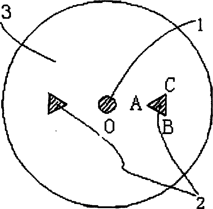
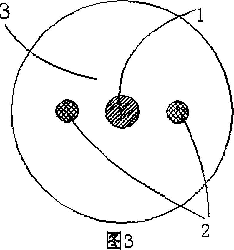
[0036] The waveguide structure of polarization maintaining fiber is as figure 1 As shown, it includes a core 1 with a circular section, and the core is covered with a cladding 3 with a circular section centered on the core, and the two sides of the core are symmetrically arranged in the cladding. The cross-sectional shape is equilateral Triangular stress element 2, the vertex A of the triangle ABC stress element is located inside the cladding and points to the center of the fiber core, the bottom edge BC of the triangular stress element is located outside the cladding and perpendicular to the radius of the fiber core, the two triangles The cross-sections of the stress elements are equal in size and equal in length to the fiber core.

[0037] The manufacturing method of the polarization-maintaining optical fiber is as follows: first, a single-mode mandrel with a diameter of 2mm is manufactured by PCVD; the doped B 2 o 3 Stress rods (SAP), doping molar concentration range 12% ...

Embodiment 2

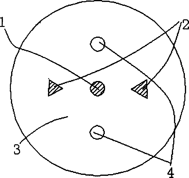
[0039] The main difference between the second embodiment and the first embodiment is that the stress element 2 whose cross-sectional shape is an isosceles triangle is arranged symmetrically on both sides of the fiber core 1 in the cladding layer 3, and the apex angle of this triangular stress element is 90° and point to the center of the fiber core, the bottom edge of the triangular stress element is located outside the cladding and is perpendicular to the radius of the fiber core, the two waist angles are 45°, and other structures are the same as in Embodiment 1.

[0040] The manufacturing method of the present embodiment is the same as that of the previous embodiment, adopting PCVD to manufacture a single-mode mandrel, the mandrel diameter is 2mm; manufacture doped stress rods with MCVD, then be processed into two sides whose length is 12.6mm (i.e. AC=AB=12.6mm), the other side is an isosceles right triangle with 17.8mm (ie BC=17.8), the mandrel and the stress rod are combine...


PUM

PropertyMeasurementUnit
angleaaaaaaaaaa
diameteraaaaaaaaaa
diameteraaaaaaaaaa

Abstract

A polarization maintaining fibre with high birefringence is composed of fibre core and cladding layer in which there are the triangular stress element arranged symmetrically at both sides of fibre core and the optional stress holes. Its preparing process includes combining core rod with stress rods by OVD technology, spraying the cladding layer, and drawing. Its advantages are simple preparing process, and high axial uniforming, strength and performance.

Description

technical field [0001] The invention relates to a high birefringence polarization-maintaining optical fiber used in the field of optical fiber communication or in the field of sensors and fiber optic devices, in particular to a structure of a high birefringence polarization-maintaining optical fiber and a manufacturing method thereof. Background technique [0002] Transverse Spatial Mode HE for Standard Single-Mode Optical Fiber Transmission 11 , are actually two orthogonal modes HE 11 x and HE 11 y The degenerate mode of (due to βx≈βy). Due to the fact that the actual single-mode fiber is not ideally circular in geometric size, and other defects include external stress, bending and torsion, etc., the modal degeneracy is destroyed. The two modal transmission constants βx and βy are different. As a result, modal birefringence is generated, resulting in a phase difference between orthogonal mode components and a transmission delay difference, that is...

Claims


Application Information

Patent Timeline
Patent Type & Authority Applications(China)
IPC IPC(8): G02B6/44
Inventor 刘有信陈伟李诗愈尹红兵朱明华王淑斌李进延
Owner FENGHUO COMM SCI & TECH CO LTD
Why Eureka
Try Eureka