Eureka AIR delivers breakthrough ideas for toughest innovation challenges, trusted by R&D personnel around the world.

A welded joint construction for a steel pipe column

A technology of steel pipe joints and steel pipes, which is applied in the direction of building structures, columns, pier columns, etc., can solve the problems of inability to quickly perform welding operations, backing plate deformation, and increased welding volume, and achieve shortened production time, good stress transmission, and reduced cost effect

Inactive Publication Date: 2004-01-14
NAKAJIMA STEEL PIPE CO LTD
View PDF1 Cites 7 Cited by
  • Summary
  • Abstract
  • Description
  • Claims
  • Application Information

AI Technical Summary

Problems solved by technology

[0006] However, if the square steel pipe column of the above-mentioned thick-walled short square steel pipe is used, the bevel portion for welding will be formed on the inside of the thick-walled short square steel pipe, which is time-consuming and expensive to manufacture.
In addition, since the welding on the inner side (the side of the backing plate) is performed with the backing plate positioned along the inner surface of the long rectangular steel pipe of a predetermined thickness from the groove portion of the thick short square steel pipe, the amount of welding increases, It is not possible to perform welding work quickly, and sometimes it is necessary to deform the backing plate (special processing)

Method used


Image

  • A welded joint construction for a steel pipe column
  • A welded joint construction for a steel pipe column
  • A welded joint construction for a steel pipe column

Examples


Embodiment Construction

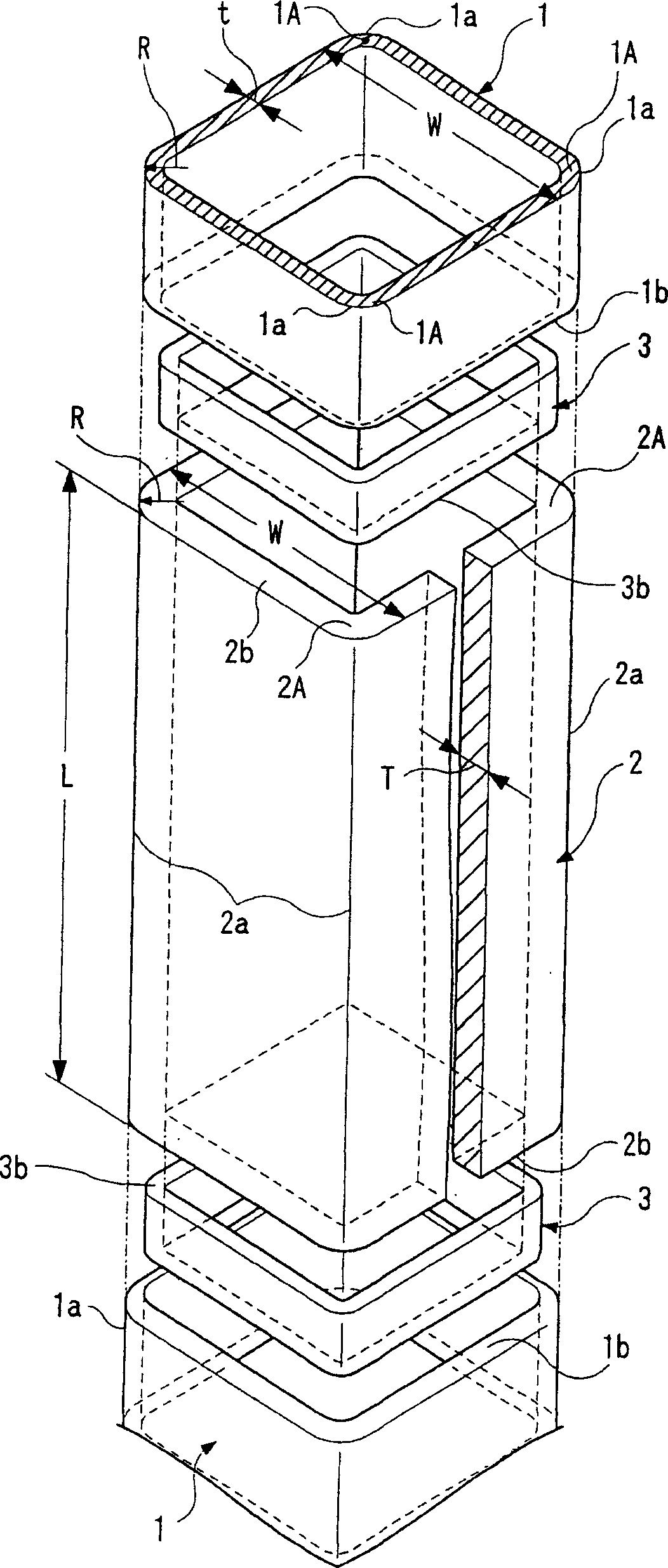
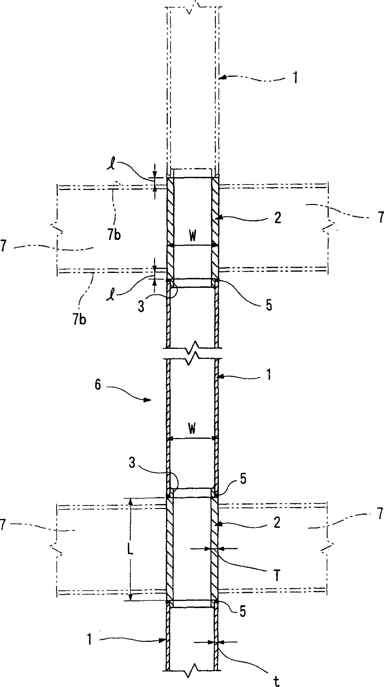
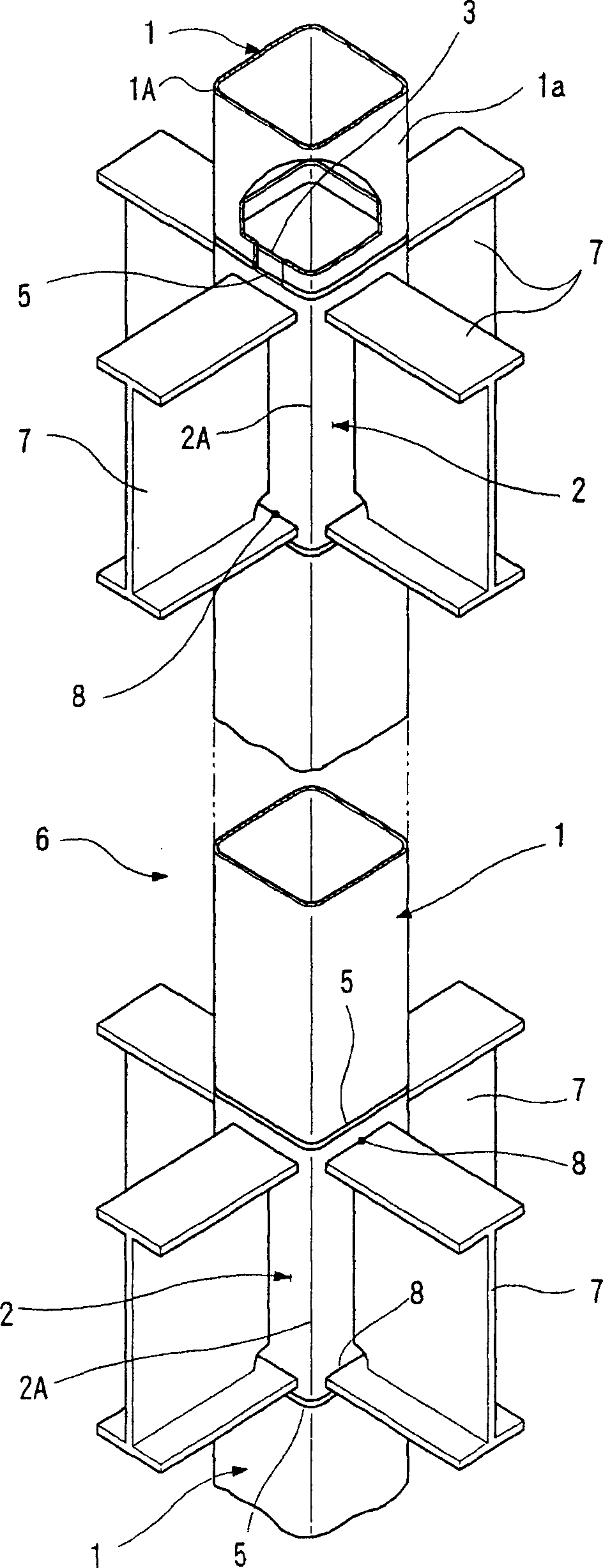
[0058] Borrow below Figure 1~Figure 8 The first embodiment of the present invention will be explained as the state of a square steel tube.

[0059] Such as figure 1 As shown, a long rectangular steel pipe (an example of a long steel pipe) 1 having a predetermined plate thickness t, and a plate thickness T thicker than the plate thickness t of the long rectangular steel pipe 1 form a plate seat area (バネルゾ一ン), a short square steel pipe (an example of a short steel pipe) 2 having a length (height) of L. Here, the predetermined plate thickness t is determined by the outer dimension W of the square steel pipe column used in accordance with the scale of the steel frame structure. For example, when the outer dimension W is 500 mm, the plate thickness t is 25 mm. In addition, the plate thickness t of the long square steel pipe 1 and the plate thickness T of the short square steel pipe 2 are, for example, 2tT.

[0060] The long square steel pipe 1 and the short square steel pipe 2 are f...


PUM


Abstract

A joint construction for a column of steel pipes comprises a long steel pipe 1 of a first thickness t and a second steel pipe 2 of a second thickness T which is greater than that of the first. The steel pipes 1,2 are formed by either cold or hot forming to have the same outer shape and diameter, and they are welded together from the outside in an arrangement in which an end surface of the long pipe 1 is opposed to an end surface of the short pipe 2 which has no bevelled portion. An inner collar 3 can be included in the joint construction and may be positioned inside the long pipe 1 so that it can be abutted against the end surface of the short pipe 2. The pipes 1,2 may either be quadrangular or cylindrical.

Description

Technical field [0001] The present invention relates to, for example, a joint structure of a steel pipe for a column used as a pillar of a steel frame structure Background technique [0002] In the prior art, steel pipes for pillars used as pillars, such as those seen in Japanese Patent Application Laid-Open No. 2001-303661, provide a thick-walled column obtained by hot forming in the plate seat area. constitute. [0003] That is, for example, cold forming is used to produce a long rectangular steel pipe with a predetermined thickness, and at the same time, after heating in a heating furnace, hot forming produces a thicker steel pipe than the long rectangular steel pipe and having a length that forms the connecting portion of the beam. Short square steel tube. Then a groove is formed on the inner side of the short square steel pipe. The thus obtained long square steel pipe and the short square steel pipe are combined by welding such as arc welding to obtain a square steel pipe co...

Claims


Application Information

Patent Timeline
IPC IPC(8): E04B1/24
CPCE04B2001/2454E04B2001/246E04B2001/2451E04B2001/2406E04B1/2403
Inventor 中岛伸中岛教雄中岛拓中岛功雄
Owner NAKAJIMA STEEL PIPE CO LTD
Why Eureka
Eureka Blog
Learn More