Synchronous rectificating device
A technology of synchronous rectification and rectification circuit, which is applied in the conversion device of output power, the conversion of AC power input to DC power output, electrical components, etc., can solve the problem that the power transmission efficiency cannot be effectively improved
- Summary
- Abstract
- Description
- Claims
- Application Information
AI Technical Summary
Problems solved by technology
Method used
Image
Examples
Embodiment Construction
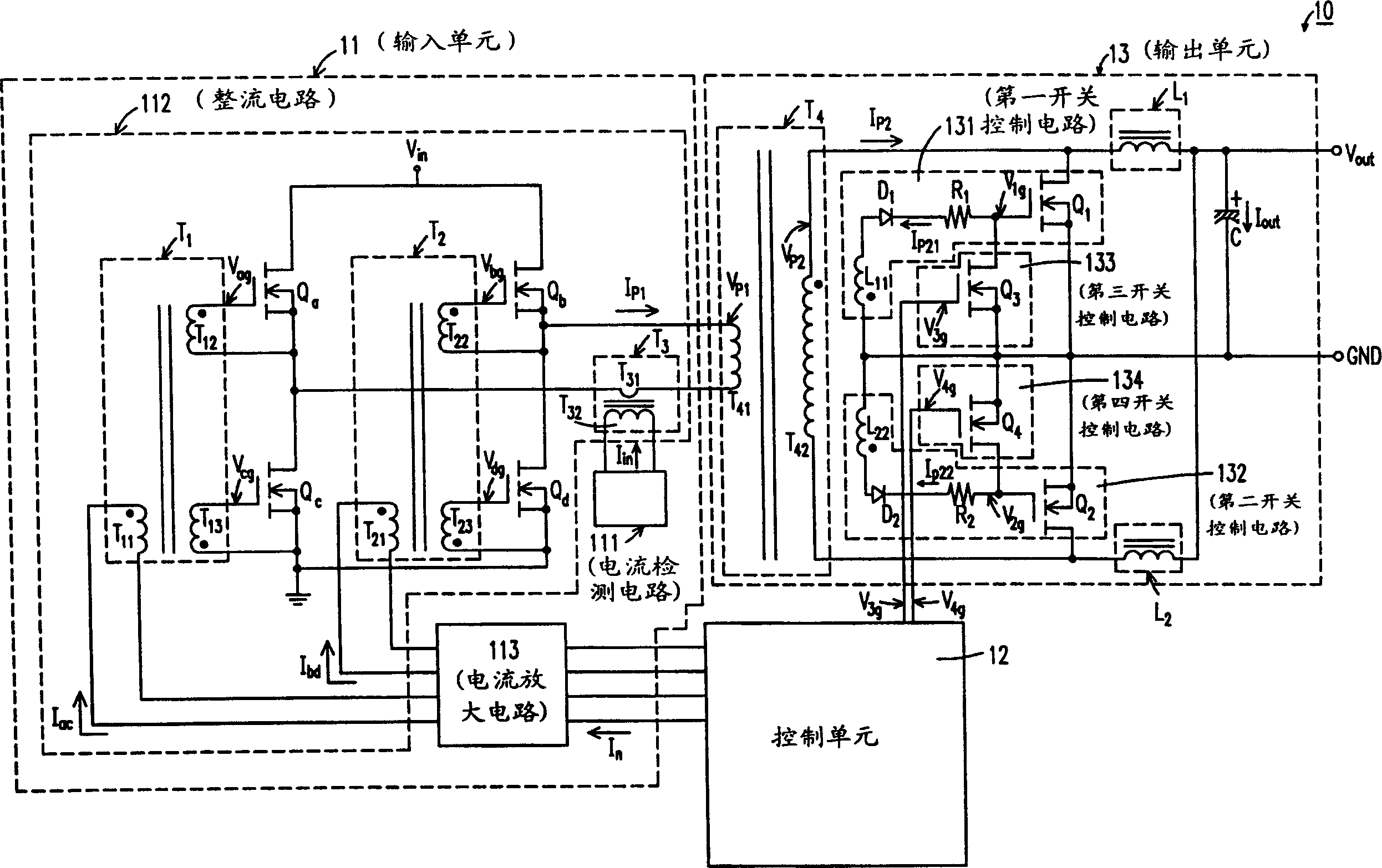
[0047] Please refer to FIG. 3 , which is a schematic diagram of a block structure of a preferred embodiment of the present invention. The synchronous rectification device 20 shown in FIG. 3 includes: an input unit 21, a control unit 22 and an output unit 23; wherein , the input unit 21 may include a signal detection circuit 211, a rectification circuit 212, a signal amplification circuit 213, a first transformer element group T1, a second transformer element group T2, a third transformer element group T3 and a bridge rectifier circuit composed of 4 transistors Qa, Qb, Qc, Qd (for example, can all be a metal oxide field effect (MOSFET) transistor); in addition, the output unit 13 includes a first filter Inductance circuit L1 (for example, can be a first filter inductor), a second filter inductor circuit L2 (for example, can be a second filter inductor), a filter capacitor circuit C (for example, can be a filter capacitor), a fourth transformer element group T4, a first, second ...
PUM
 Abstract
Description
Claims
Application Information
 - R&D
- Intellectual Property
- Life Sciences
- Materials
- Tech Scout
- Unparalleled Data Quality
- Higher Quality Content
- 60% Fewer Hallucinations
Browse by: Latest US Patents, China's latest patents, Technical Efficacy Thesaurus, Application Domain, Technology Topic, Popular Technical Reports.
© 2025 PatSnap. All rights reserved.Legal|Privacy policy|Modern Slavery Act Transparency Statement|Sitemap|About US| Contact US: help@patsnap.com


