Electric resistance measuring connector and measuring device and measuring method for circuit board electric resistance

A resistance measurement and resistance measurement technology, applied in the direction of measuring resistance/reactance/impedance, testing/measuring connectors, measuring devices, etc. Achieving sufficient electrical conductivity, etc.

Inactive Publication Date: 2004-02-04
ISC CO LTD
View PDF2 Cites 28 Cited by
  • Summary
  • Abstract
  • Description
  • Claims
  • Application Information

AI Technical Summary

Problems solved by technology

[0019] However, anisotropic conductive elastomers with a large thickness have low pressure-sensitive conductivity sensitivity, so sufficient conductivity cannot be achieved in the thickness direction of the anisotropic conductive elastomer unless a considerable amount of pressure is applied to the anisotropic conductive elastomer in its thickness direction. big strain
Therefore, it is difficult to ensure that the required electrical connection is realized for the detected electrodes having a small protrusion height among a large number of detected electrodes in the tested circuit board. Performs specified resistance measurements with high precision

Method used


Image

  • Electric resistance measuring connector and measuring device and measuring method for circuit board electric resistance
  • Electric resistance measuring connector and measuring device and measuring method for circuit board electric resistance
  • Electric resistance measuring connector and measuring device and measuring method for circuit board electric resistance

Examples


example 1

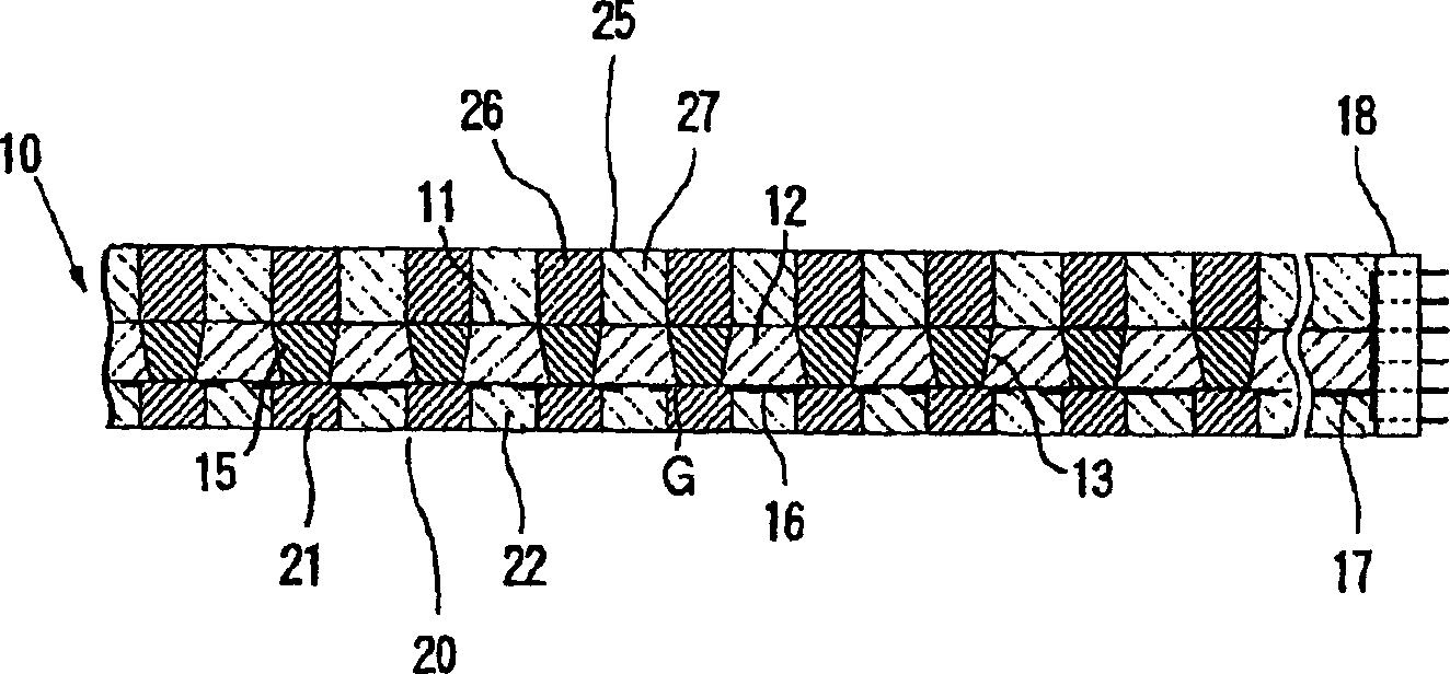
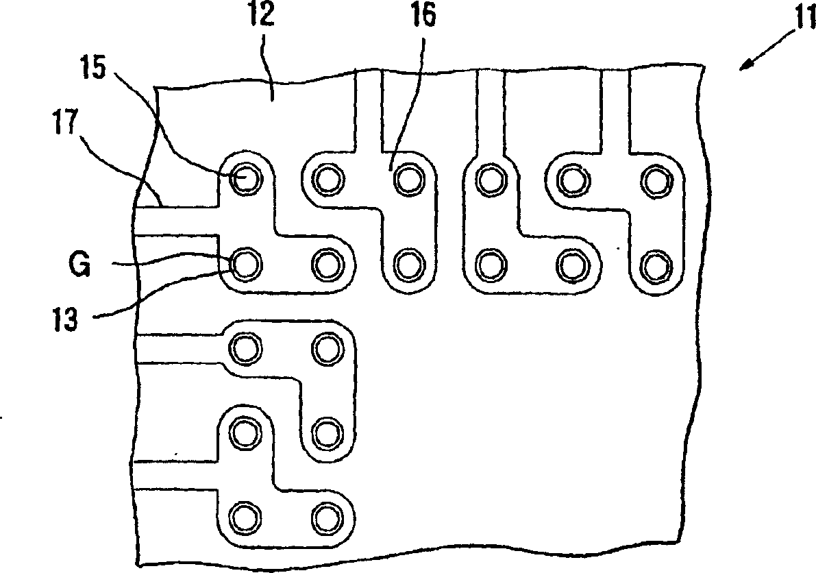
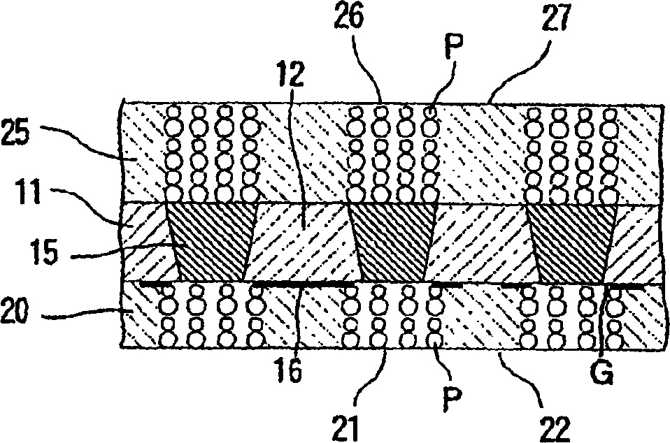
[0235] according to Figure 16 and 17 With the structure shown in , a circuit board resistance measuring device was produced under the following conditions. (1) Upper side configuration: [One side circuit board for detection on one side]

[0236] The shape and size of the detection electrode:

[0237] Round, 0.12mm in diameter.

[0238] Detect the spacing between electrodes:

[0239] 0.25mm. [Resistance measurement connector]

[0240] Composite electrode sheet: insulating sheet material: polyimide; insulating sheet thickness: 0.05mm; passing hole shape: truncated cone; front opening diameter: 0.08mm; back opening diameter: 0.12mm; movable electrode material : Nickel; Static electrode material: Copper; Number of through-hole openings surrounded by a stationary electrode; minimum one, maximum 40.

[0241] Front-side anisotropic conductive material layer: elastomer material; silicone rubber; thickness: 0.05 mm; diameter of part forming the conductive path: 0.1 mm...

reference example 2

[0259] It is clear from the results shown in Table 1 that according to the resistance measuring device according to Example 1, resistance can be measured with a small error range (±10 mΩ), which is equivalent to the resistance measured by the four-probe method of measuring resistance with probes, From the standpoint of practical use, however, this achieves a sufficiently high accuracy.

[0260] On the other hand, the resistance measuring device according to Comparative Example 1 caused a large error compared with the resistance value measured by the four-probe method of measuring resistance with probes.

[0261] Effect of the present invention


PUM


Abstract

Disclosed herein are a connector for measurement of electric resistance, by which an electric resistance-measuring apparatus capable of surely performing expected measurement of electric resistance with high precision even to a circuit board having small-sized, protruding electrodes to be inspected, a scatter of projected heights of said electrodes being great, and easy to produce can be constructed, and electric resistance-measuring apparatus using this connector and method of measurement. The connector has a composite electrode sheet having an insulating sheet body in which through-holes have been formed corresponding to electrodes to be inspected, movable electrodes supported movably in a thickness-wise direction within the through-holes, and stationary electrodes each formed in the vicinity of openings of the through-holes on a front surface of the insulating sheet body in a state coming into no contact with the movable electrodes, front-side and back-side anisotropically conductive elastomer layers respectively laminated on the front surface and back surface of the composite electrode sheet, and an external leading terminal electrically connected to the stationary electrodes. The movable and stationary electrodes are electrically connected at the same time to corresponding electrodes to be inspected through the front-side anisotropically conductive elastomer layer.

Description

technical field [0001] The invention relates to a connector for measuring resistance, a resistance measuring device and a measuring method for a circuit board. Background technique [0002] In recent years, due to the need to increase the signal transmission speed in electronic parts, low resistance of wiring between electrodes of circuit boards has been required to manufacture LSI (Large Scale Integration) components such as BGA and CSP. Therefore, it is particularly important to measure the resistance of the wiring between the electrodes of such a circuit board with high precision in the electrical inspection of the circuit board. [0003] Such as Figure 22 As shown in , in the resistance measurement of the circuit board, such a means has been used previously, in which the probes PA and PD for supplying current and the probes PB and PC for voltage measurement are respectively pressed on the two tested The electrodes 91 and 92 are brought into con...

Claims


Application Information

Patent Timeline
Patent Type & Authority Applications(China)
IPC IPC(8): G01R1/04G01R1/067G01R1/073G01R27/02H01R11/01H05K3/00
CPCG01R1/07307G01R1/06755G01R1/07371H01R2201/20G01R1/07328G01R1/0416G01R27/02
Inventor 木村洁
Owner ISC CO LTD
Why Eureka
Try Eureka