Supercharge Your Innovation With Domain-Expert AI Agents!

Medical image catching system, server device and method for control said system

A medical image and image generation device technology, applied in the field of medical image capture system, can solve problems such as cumbersome operation and achieve the effect of simplifying software management

Inactive Publication Date: 2004-02-11
GE MEDICAL SYST GLOBAL TECH CO LLC
View PDF0 Cites 5 Cited by
  • Summary
  • Abstract
  • Description
  • Claims
  • Application Information

AI Technical Summary

Problems solved by technology

[0005] However, for example, when multiple X-ray CT systems are installed in a hospital, even if the above-mentioned network technology is adopted, it is still necessary to download the latest version of the application software and install it in the console of the X-ray CT system, resulting in obvious cumbersome operation

Method used


Image

  • Medical image catching system, server device and method for control said system
  • Medical image catching system, server device and method for control said system
  • Medical image catching system, server device and method for control said system

Examples


no. 1 example

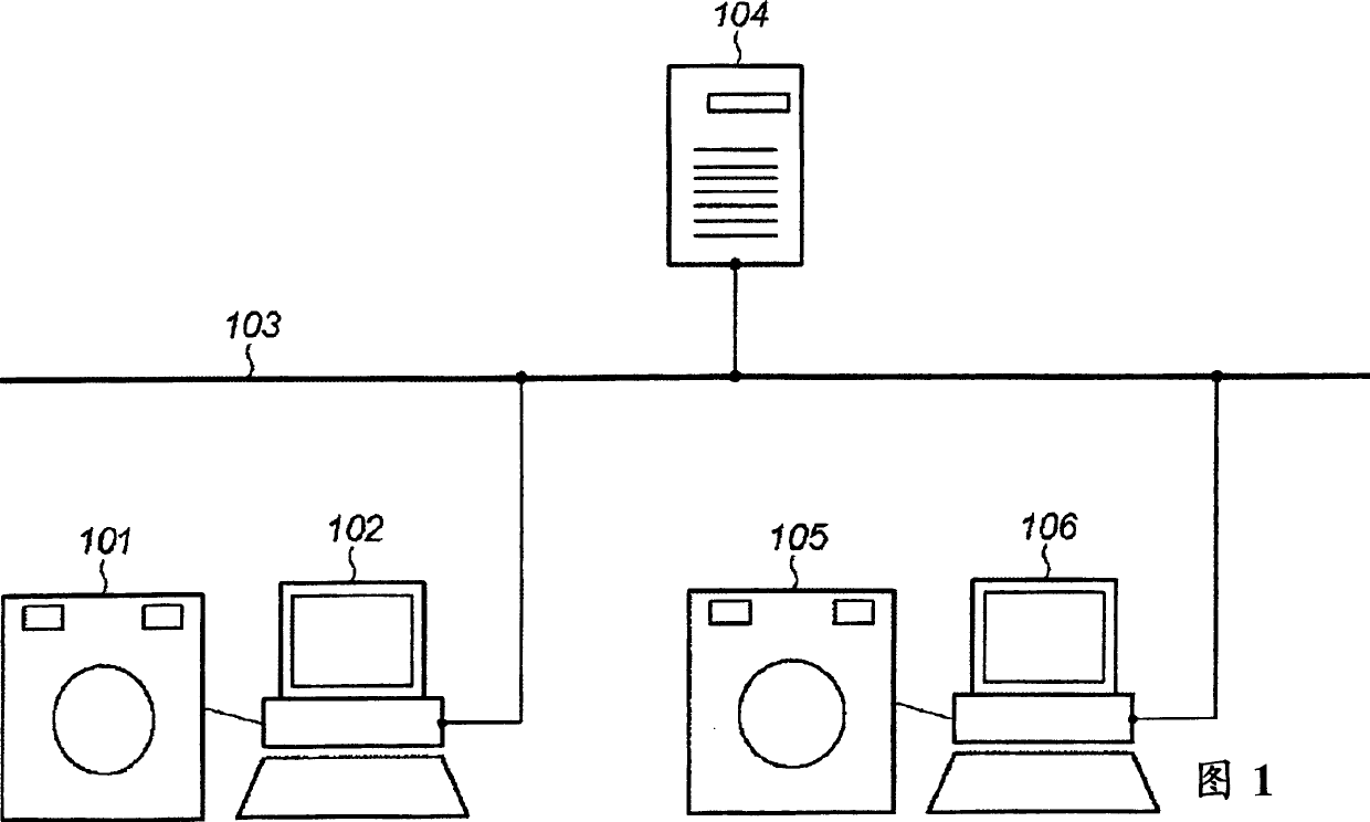
[0039] FIG. 1 illustrates a general configuration of an X-ray CT system according to the present embodiment. Reference numerals 101 and 105 each represent a gantry device, reference numerals 102 and 106 each represent a console, reference numeral 103 represents a network such as an optical fiber, and reference numeral 104 represents a server (server device). Although there are two sets of console and gantry devices connected to the network 103 in FIG. 1 , the number is not limited to two.

[0040] The gantry device 101 (105) has the function of irradiating the object to be inspected with X-rays according to the scanning plan sent from the console 102 (106), and collecting projection data (imaging data) according to the X-rays penetrating the object to be inspected. The projection data is sent to console 102 (106). The console 102 (106) sends the received projection data to the server 104 via the network 103, and the server 104 performs image reconstruction processing using th...

no. 2 example

[0065] Although the number of servers is only one in the first embodiment, a plurality of servers are connected to the network in this embodiment. Specifically, each company has its own server that stores its own application software, and connects the server to the network. This enables many consoles to use applications from many different companies. The system of this embodiment will be described below.

[0066] Fig. 5 shows a general configuration of the X-ray CT system according to the present embodiment. Reference numerals 501, 502, and 503 denote hospitals, each of which has an X-ray CT apparatus including gantry devices (501a, 502a, 503a) and operating tables (501b, 502b, 503b). In each hospital, as is known in the art, the projection data of the test object obtained by the gantry device is sent to the operator's station, which receives the data.

[0067] The consoles in each hospital can be connected to a network 510, such as Ethernet or LAN, through which the consol...

no. 3 example

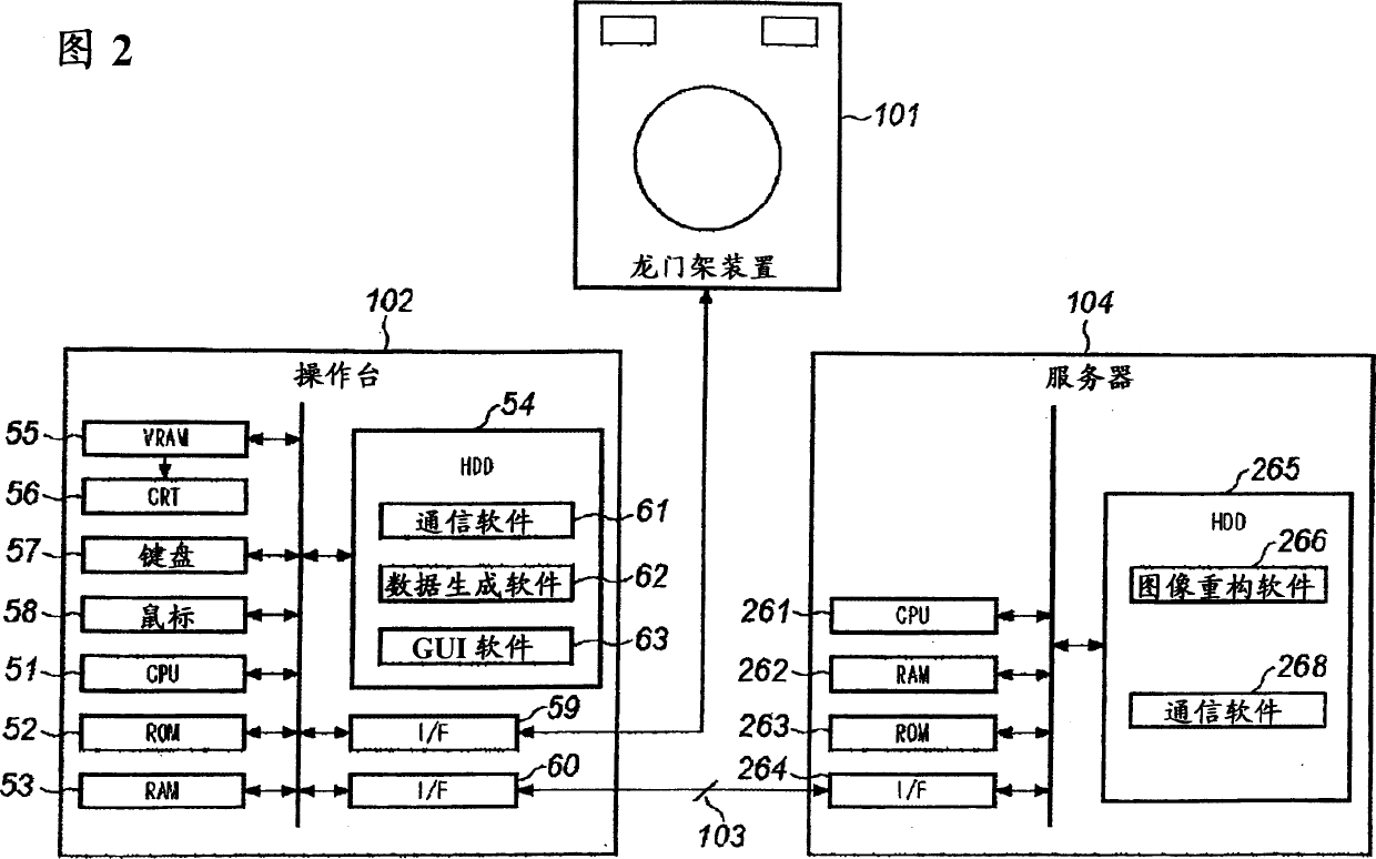
[0083] Although the multiple application software included in the console and the server are shown as separate in the above embodiments, the present invention is not limited thereto, and these application software can also be combined for the console and the server respectively. For example, communication software 61, data generation software 62, and GUI software 63 can be combined into one application software, and image reconstruction software 266 and communication software 268 can be combined into one software.


PUM


Abstract

For the purpose of simplifying software management, an operation console reads projection data at Step S401, generates transmitted data at Step S402, and transmits the data to a server at Step S403. The server receives the transmitted data at Step S451, and executes error correction processing on raw data at step S452. Next, at Step S453, image reconstruction processing is executed based on the raw data corrected at Step S452 to produce an X-ray tomographic image. At Step S454, the data of the X-ray tomographic data is transmitted to the operation console. The operation console then receives the data of the X-ray tomographic image at Step S404, and saves the received data of the X-ray tomographic image or displays it as an image at Step S405.

Description

technical field [0001] The present invention relates to a medical image capture system, such as an X-ray CT (Computed Tomography) system, for collecting imaging data of a test object and providing a medical image based on the data. Background technique [0002] An X-ray CT system generally includes a gantry device and an operating table. The gantry device generally has the functions of irradiating an object to be inspected with X-rays, detecting X-rays penetrating the object to be inspected, and collecting projection data of the object to be inspected. The console has the functions of specifically setting the scan (scan plan) to be performed by the gantry device, sending the scan plan to the gantry device, performing image reconstruction processing based on the projection data sent from the gantry device, and generating a tomographic analysis image of the inspection object . Therefore, the console has application software for setting the scan plan, sending the scan plan, p...

Claims


Application Information

Patent Timeline
Patent Type & Authority Applications(China)
IPC IPC(8): A61B5/00A61B6/03G06Q30/04G06Q30/06G06Q50/00G06Q50/10G06T1/00G16H10/60H05G1/00
CPCG06F19/321G06Q50/24G06F19/3418G06F19/328G06Q10/10G16H40/67G16H30/20
Inventor 萩原明
Owner GE MEDICAL SYST GLOBAL TECH CO LLC
Features
  • R&D
  • Intellectual Property
  • Life Sciences
  • Materials
  • Tech Scout
  • Unparalleled Data Quality
  • Higher Quality Content
  • 60% Fewer Hallucinations
Learn More