Laser micro function digital microscope device

A digital microscopy and laser technology, applied in the field of microscopy, can solve problems such as difficult control and difficult operation.

Inactive Publication Date: 2004-02-11
XI'AN INST OF OPTICS & FINE MECHANICS - CHINESE ACAD OF SCI
View PDF0 Cites 6 Cited by
  • Summary
  • Abstract
  • Description
  • Claims
  • Application Information

AI Technical Summary

Problems solved by technology

These microscopic treatments and operations can be realized by mechanical methods,

Method used


Image

  • Laser micro function digital microscope device
  • Laser micro function digital microscope device

Examples


Embodiment Construction

[0011] The present invention will be described in further detail below in conjunction with the accompanying drawings and embodiments, but the present invention is not limited to these embodiments.

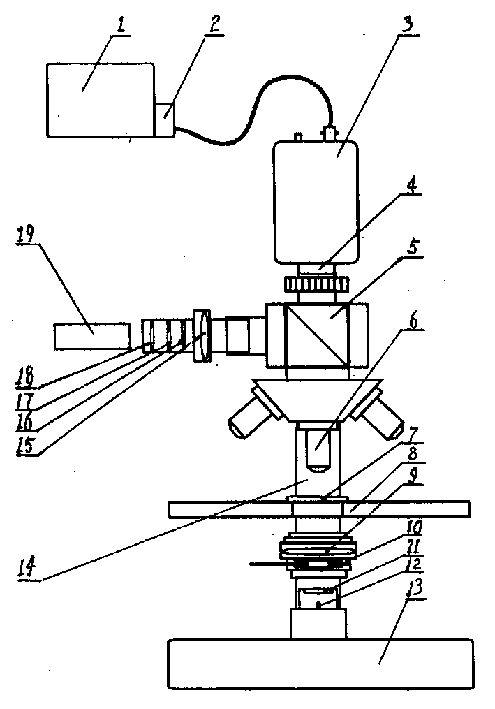
[0012] exist figure 1 Among them, the laser microaction digital microscope device of the present embodiment consists of a computer 1, an image acquisition card 2, a CCD camera 3, an analyzer 4, a beam splitting prism 5, a microscope objective lens 6, an object stage 8, a condenser lens 9, a variable Diaphragm 10, frosted glass 11, light emitting diode 12, base 13, cantilever 14, focusing lens 15, polarizer 16, attenuator 17, electric shutter 18, laser 19 are connected to form.

[0013] The base 13 is integrated with the cantilever 14, and the cantilever 14 is fixedly connected with a stage 8 with a threaded fastener. The stage 8 can place the sample 7 to be processed, and the stage 8 can move in the direction of the XYZ coordinate axis. Two-dimensional plane movement in the direct...


PUM


Abstract

The laser micro function digital microscope device includes pedestal, cantilever connected integrally with the pedestal, object stage on the cantilever, laser focusing mechanism on the cantilever, laser set on one side of the laser focusing mechanism, digital image acquisition mechanism set on the laser focusing mechanism, and lighting and reading mechanism set on the pedestal and cantilever. The laser micro function digital microscope device is superior to common optical microscope likely leading fatigue of human eyes, and can act directly on the observed microscopic matter and produce digital document of the observed process. The present invention has wide application in biomedicine and other fields.

Description

technical field [0001] The invention belongs to the technical field of microscopes, and in particular relates to a laser microaction digital microscope device. Background technique [0002] Light microscopy has a wide range of applications in biology, medicine, medicinal chemistry, agriculture, industry, and related fields. Ordinary optical microscopes magnify microscopic objects through microscopic objective lenses and eyepieces. Human eyes can only observe microscopic objects through the eyepieces, but cannot record and save them. A photographic microscope can capture static images of the observed object by setting a camera in the eyepiece part, but it cannot capture the dynamic change process of the microscopic object. Digital microscopes use CCD or CMOS image sensors as image acquisition devices, which can capture the dynamic changes of microscopic objects, but cannot perform microscopic processing and manipulation of the observed objects. In actual work, we not only n...

Claims


Application Information

Patent Timeline
IPC IPC(8): G02B21/00G02B21/08G02B21/36
Inventor 姚保利雷铭
Owner XI'AN INST OF OPTICS & FINE MECHANICS - CHINESE ACAD OF SCI
Why Eureka
Try Eureka