Synchronous motor control method and device thereof

A technology of synchronous motor and control method, which is applied in the direction of AC motor control, electronic commutation motor control, current controller, etc., which can solve the problems of reduced efficiency, difficulty in fine-grained control, and small voltage phase control range to achieve voltage utilization. Improve and suppress speed fluctuations and achieve controllable effects

Inactive Publication Date: 2004-03-03
DAIKIN IND LTD
View PDF0 Cites 20 Cited by
  • Summary
  • Abstract
  • Description
  • Claims
  • Application Information

AI Technical Summary

Problems solved by technology

[0006] However, in the case of method (1), because of the use of current control, the voltage utilization rate cannot be improved, so it is necessary to reduce the motor windings to reduce the induced voltage, resulting in defects such as reduced efficiency
Also, since the position is shifted while the motor is running, even if the torque control is performed to suppress the speed fluctuation in one revolution, a sufficient damping effect cannot be obtained.
[0007] In the case of using method (2), due to the observation of the induced voltage of the non-energized phase, the energized width cannot be expanded, and there are defects such as that the voltage utilization rate cannot be improved.
In addition, there is also the disadvantage that the control range of the voltage phase is small, and the IPM (brushless DC motor with a rotor with an embedded magnet structure) cannot be efficiently operated.
Moreover, because it is necessary to detect the rotational position of every 60° as much as possible, there is also a defect that it is difficult to fine-tune the control

Method used


Image

  • Synchronous motor control method and device thereof
  • Synchronous motor control method and device thereof
  • Synchronous motor control method and device thereof

Examples


Embodiment Construction

[0109] Hereinafter, embodiments of the synchronous control method and device thereof according to the present invention will be described in detail with reference to the accompanying drawings. In the following embodiments, the case of controlling the output voltage of the inverter will be described, but the output current of the inverter may also be controlled.

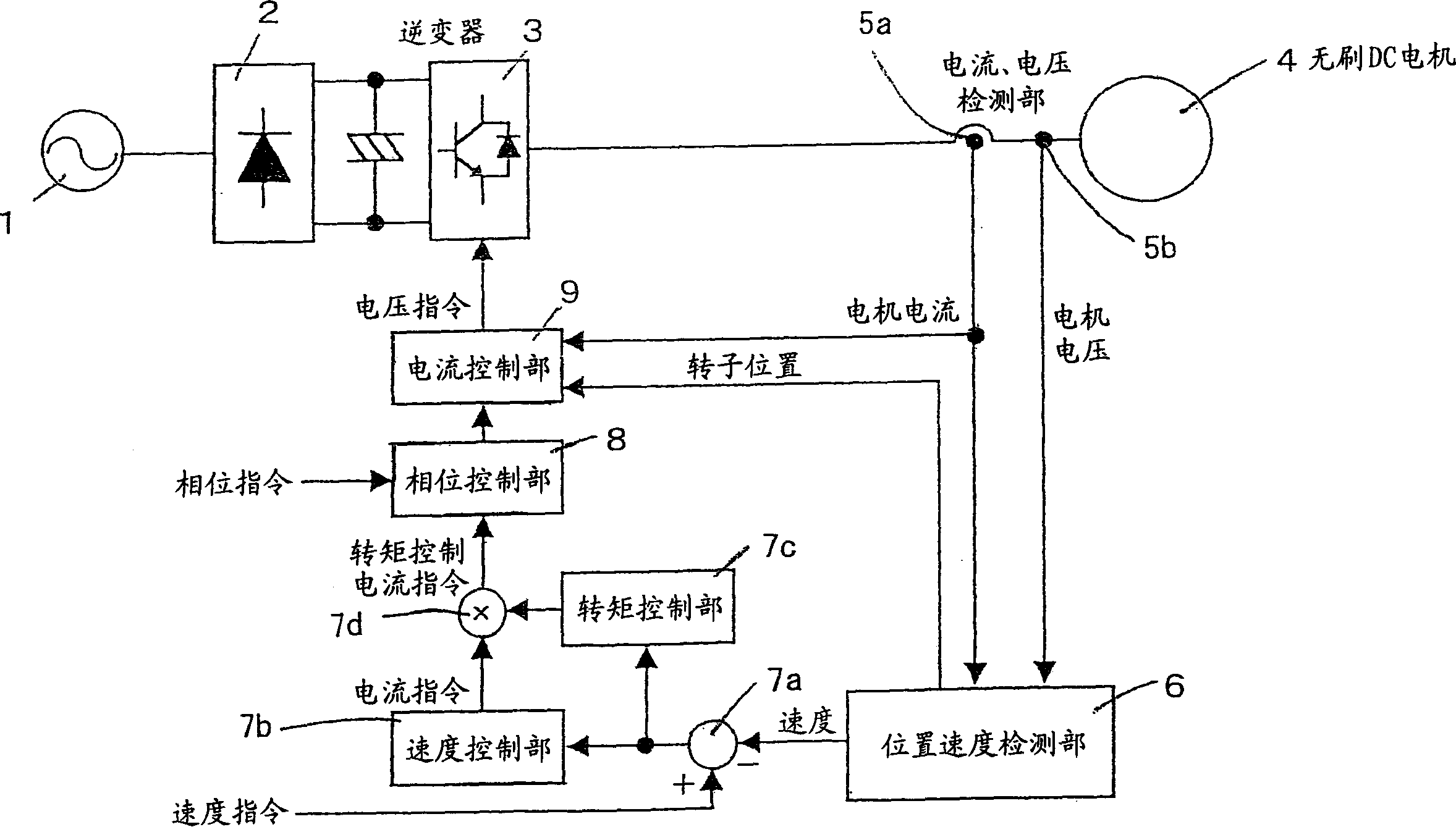
[0110] figure 1 It is a block diagram showing an embodiment of the synchronous motor control device of the present invention.

[0111] The synchronous motor control device has: a converter 2, which uses the AC power supply 1 as an input to obtain a direct current; an inverter 3, which takes the direct current as an input to obtain an alternating current, and provides it to a synchronous motor 4 which is a kind of synchronous motor; current detection The part 5a detects the motor current supplied to the synchronous motor 4; the voltage detection unit 5b detects the terminal voltage of the synchronous motor 4; the posi...


PUM


Abstract

The invention provides a synchronous motor control device comprising a current detection unit for detecting current supplied to the synchronous motor, a voltage detection means for detecting a terminal voltage, a position / speed detection unit for computing the rotation speed and rotation position of a rotor from motor model-set current and voltage, a speed difference calculating unit for calculating the difference between the detected speed and an externally-given speed command, a speed control unit for computing a current command from the speed difference so that an average speed agrees with the speed command, a torque control unit for computing a current amplifying modulation signal from the speed difference so as to correct a current command, a multiplying unit for multiplying the current command by the current amplifying modulation signal to calculate a torque control current command, a phase control unit for computing a final current command from the torque control current command and an externally-given phase command, and a current control unit for computing a voltage command from the detected rotor position, motor current and final current command to supply it to an inverter.

Description

technical field [0001] The present invention relates to a synchronous motor control method and its device, in particular to a motor module used to detect the rotational position of the rotor, even in the case of load fluctuations, speed command values, and torque command fluctuations, high A new synchronous motor control method and device for precisely controlling a synchronous motor. Background technique [0002] In the past, although synchronous motors were used as the driving source of various equipment, it was required to increase the voltage utilization rate of the synchronous motor, that is, to expand the operating range and improve efficiency, improve controllability, and reduce noise through over-modulation. Use sensors that detect the rotational position of the rotor to improve reliability, reduce cost, and increase the granularity of sensorless control. [0003] In addition, as synchronous motor control methods satisfying such requirements, there are: [0004] (1...

Claims


Application Information

Patent Timeline
Patent Type & Authority Applications(China)
IPC IPC(8): H02P6/00H02P6/08H02P6/10
CPCH02P6/002H02P25/083H02P6/085H02P6/10H02P6/28H02P25/089
Inventor 前田敏行小坂学喜多正信
Owner DAIKIN IND LTD
Why Eureka
Try Eureka