Dehumidifying method

A technology of evaporator and condenser, which is applied in the direction of heating mode, machine operation mode, separation method, etc., and can solve problems such as failure to reach 0°C and unstable operation state

Inactive Publication Date: 2004-03-17
ZHONGSHAN TOPG ECOLOGY TECH
View PDF0 Cites 2 Cited by
  • Summary
  • Abstract
  • Description
  • Claims
  • Application Information

AI Technical Summary

Problems solved by technology

[0007] As can be seen from the humidity-air diagram, the lowest possible dew point temperature obtained by the aforementioned existing cooling dehumidification method is about 5°C, and cannot reach below 0°C
If the air operating line deviates from the saturation temperature curve, the operating state (refrigeration cycle) will be unstable

Method used


Image

  • Dehumidifying method
  • Dehumidifying method
  • Dehumidifying method

Examples


Embodiment Construction

[0020] Embodiments of the present invention will be described in detail below with reference to the drawings.

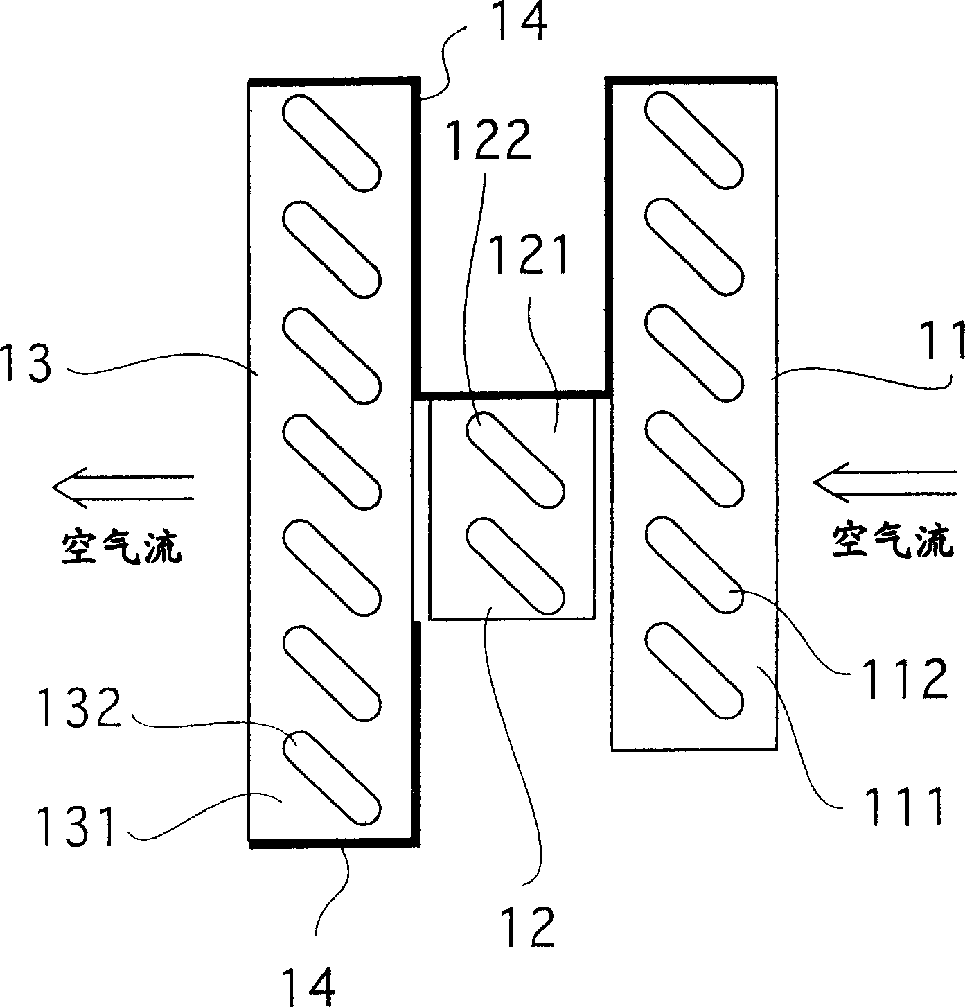
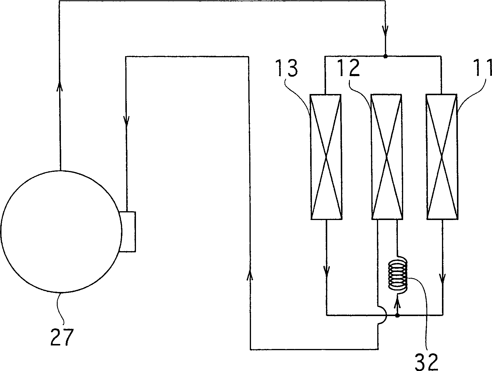
[0021] figure 1 Embodiments of the present invention are disclosed. In this embodiment, a preheating condenser 11 , an evaporator 12 , and a reheating condenser 13 are vertically arranged sequentially from the windward side to dehumidify the indoor air. In addition, although not shown in the drawings, a blower capable of forming an air flow from the preheat condenser 11 to the reheat condenser 13 is disposed on the leeward side of the reheat condenser 13 . In addition, reference numeral 14 in the figure is a baffle for blocking the passage of air.

[0022] The preheating condenser 11 and the reheating condenser 13 are divided into two parts by dividing one condenser into two parts, respectively arranged on the windward side and the downwind side of the evaporator 12, so as shown in FIG. The refrigerant flow is in a parallel relationship. In addition, reference nu...


PUM


Abstract

A dehumidifying method capable of increasing a dehumidification amount by lowering the lowest dew point temperature of a device to near 0 C, comprising the steps of disposing a preheat condenser, an evaporator, and a reheat condenser so that a sensible heat factor is less than 0.5, and condensing, dropwise, the moisture in the air on the surface of the evaporator for dehumidification, whereby, since the condensation load of the condenser is lowered and, accordingly, a condensation temperature and an evaporation temperature are lowered, a temperature difference between an air flow and the surface of the evaporator is increased, and the dropwise condensation of the moisture is promoted to increase the dehumidification amount.

Description

technical field [0001] The present invention relates to a dehumidification method for cooling and dehumidifying indoor air by using an evaporator. Specifically, it relates to a dehumidification method capable of greatly increasing the dehumidification capacity compared with conventional dehumidification methods. Background technique [0002] The dehumidification method of the existing dehumidifier has various methods such as cooling type, compression type, absorption type, and adsorption type. Among them, the cooling type is also called the direct expansion coil type. Its principle is to cool the air with a compression refrigerator to reduce the saturated water vapor pressure and condense the moisture in the air to achieve the purpose of dehumidification. This method is widely used in household dehumidifiers or business dehumidifiers due to the advantage of low equipment cost. [0003] As shown in FIG. 5, a conventional cooling dehumidifier has an evaporator 1 arranged on t...

Claims


Application Information

Patent Timeline
IPC IPC(8): B01D53/26F24F1/02F24F3/153F25B29/00
CPCF24F3/153
Inventor 佐藤近义
Owner ZHONGSHAN TOPG ECOLOGY TECH
Why Eureka
Try Eureka