Thermal energy self-supply technology and equipment for carbon ammine production change system

A technology for transforming systems and heat energy, applied in the direction of ammonium carbonate/acid carbonate, etc., can solve problems such as unreasonable flow of gas and water, insufficient and reasonable use of heat, loss of heat energy, etc., to achieve Realize self-supply of heat energy and improve heat exchange efficiency

Inactive Publication Date: 2004-03-24
陶维君
View PDF0 Cites 1 Cited by
  • Summary
  • Abstract
  • Description
  • Claims
  • Application Information

AI Technical Summary

Problems solved by technology

The working method of this conversion system needs to use another boiler. Although the heat generated in the conversion process has been used through multiple heat exchanges, the efficiency is affected because the heat exchange is outside the conversion furnace and the

Method used


Image

  • Thermal energy self-supply technology and equipment for carbon ammine production change system
  • Thermal energy self-supply technology and equipment for carbon ammine production change system
  • Thermal energy self-supply technology and equipment for carbon ammine production change system

Examples


Embodiment Construction

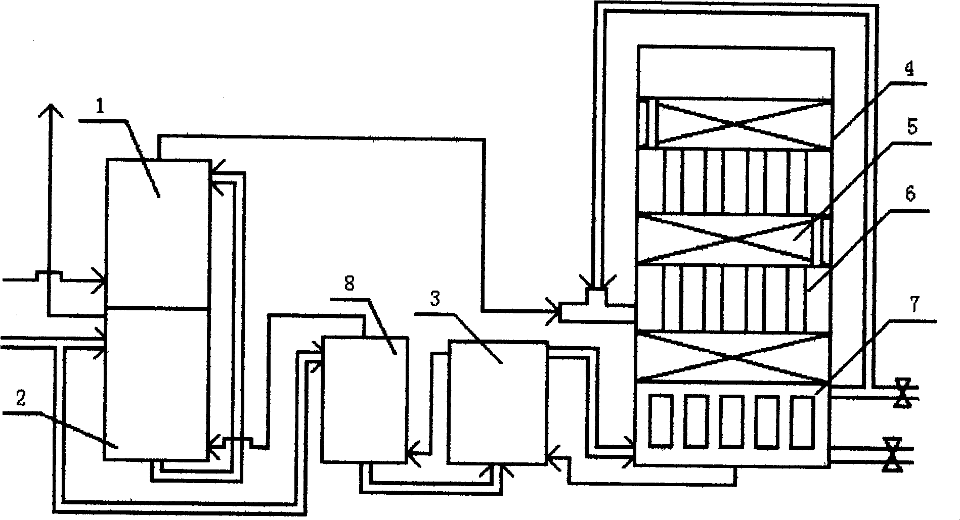
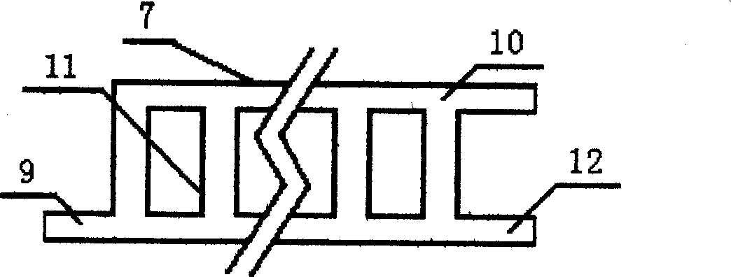
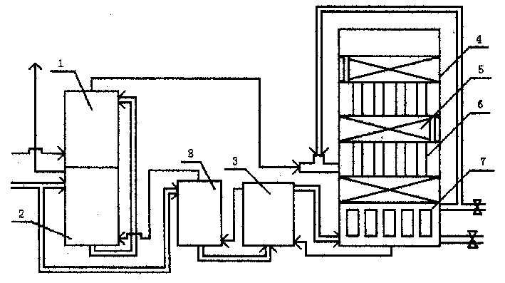
[0012] Such as figure 1 As shown, the conversion system is composed of a saturation tower 1, a hot water tower 2, a heat exchange device 3, and a shift furnace 4. The shift furnace 4 has more than two stages of contact with the coal seam 5. This embodiment is set according to the most common three stages. There is a preheating water tower 8 between the tower 2 and the heat exchange device 3. There is an internal heat exchange device 6 or a steam generation heat exchange device 7 below the catalyst layer 5 in the converter 4. In this embodiment, the bottom part of the catalyst layer 5 is the steam generation heat The exchange device 7, the bottom of the upper two catalyst layers 5 is an internal heat exchange device 6, the semi-water gas from the previous system enters the saturation tower 1, and the demineralized water from the previous system enters the hot water tower 2 and the preheating water tower 8 respectively. The semi-water gas mixture from the saturation tower 1 ente...


PUM


Abstract

A Preheat water tower using for the heat exchanging is mounted inside the transformation furnace instead of the furnace outside, in production of ammonium bicarbonate, thus the supplement of water steam is from inner system, the outer boiler is cut out.

Description

Technical field [0001] The invention relates to a production process and equipment for ammonia bicarbonate of chemical fertilizer, in particular to an energy-saving and consumption-reducing process of a semi-water gas conversion system in the production process. Background technique [0002] A large amount of thermal energy is used in the whole production process of ammonia bicarbonate, and the conversion system requires a large amount of thermal energy to supply the conversion system with water vapor and maintain the conversion temperature. The function of the conversion system is to convert the semi-water gas of the previous system into CO2 and H2 through contact with coal for the next carbonization system. The working mode of the existing conversion system is: the semi-water gas sent from the gas-making system, which is pressurized to an appropriate pressure, enters the saturation tower, sprays heated water and steam into the saturation tower to form a mixed gas, and then...

Claims


Application Information

Patent Timeline
IPC IPC(8): C01C1/26
Inventor 陶维君
Owner 陶维君
Why Eureka
Try Eureka