
Rotating transfer mechanism and zooming camera having the same

A liquid crystal display device and drive circuit technology, applied in the direction of transistors, static indicators, improved amplifiers to improve efficiency, etc., can solve the problems of power consumption, low conversion rate of excitation amplifiers, etc.

Inactive Publication Date: 2004-03-31
SAMSUNG ELECTRONICS CO LTD
View PDF1 Cites 13 Cited by
  • Summary
  • Abstract
  • Description
  • Claims
  • Application Information

AI Technical Summary

Problems solved by technology

That is, it is preferable to drive amplifiers with low slew rates in terms of power consumption
[0022] Since the driver amplifier for driving the LCD device according to the prior art uses a fixed slew rate regardless of the variation in the output voltage, power is unnecessarily consumed

Method used


Image

  • Rotating transfer mechanism and zooming camera having the same
  • Rotating transfer mechanism and zooming camera having the same
  • Rotating transfer mechanism and zooming camera having the same

Examples


Embodiment Construction

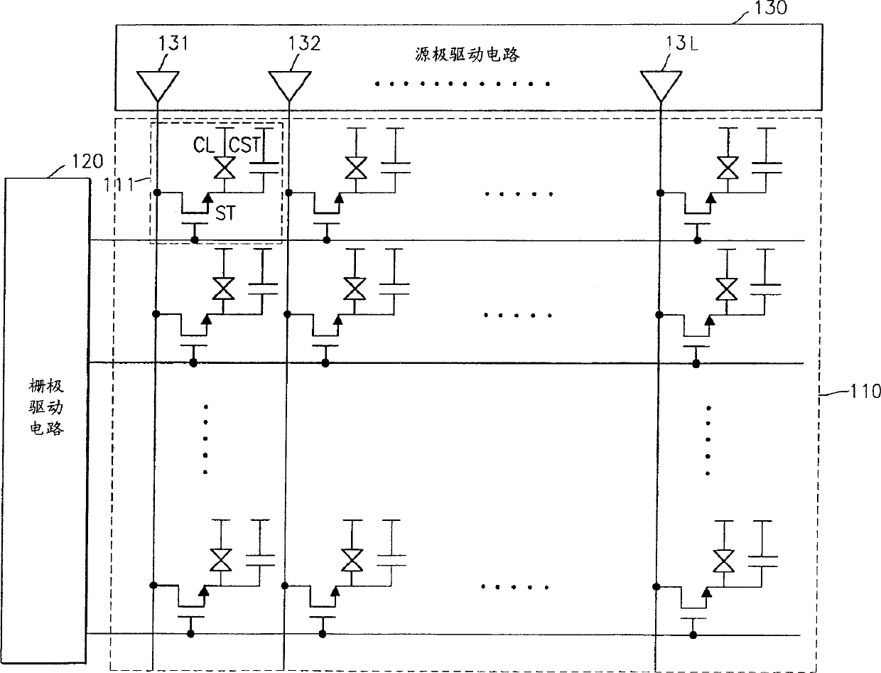
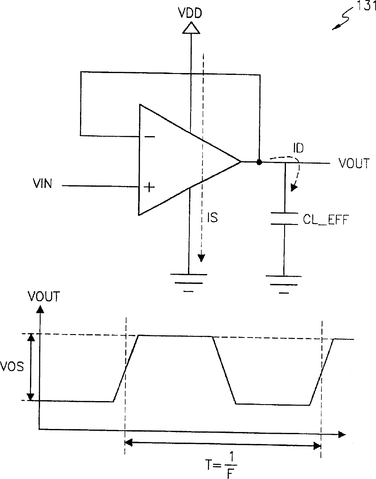
[0046] Fig. 5 is a schematic diagram of a driving unit whose slew rate is adaptively controlled according to one embodiment of the present invention. The drive unit corresponds to the driver amplifiers 131 to 13L, which are actually the channel terminals of the liquid crystal in the source driver circuit 130 shown in FIG. 1 . A drive unit is installed in each channel. However, the drive unit of the present invention is not a circuit including only a conventional driver amplifier, but a drive circuit having a driver amplifier whose slew rate is controlled and an additional circuit for controlling a slew rate.

[0047] Referring to FIG. 5, a driving unit 200 according to an embodiment of the present invention includes a driver amplifier 210 and a bias control voltage generator 220, and the slew rate of the driving unit is adaptively controlled.

[0048] Driver amplifier 210 amplifies or buffers the input voltage VIN to generate an output voltage VOUT that is applied to a liquid...


PUM


Abstract

Provided are a circuit and method for driving a liquid crystal display device using low power. The circuit includes a display data latch, a gamma decoder, and a driver cell circuit. The display data latch latches display data from a memory. The gamma decoder receives a plurality of gray scale voltages, and selects and outputs one of the plurality of gray scale voltages in response to the display data. The driver cell circuit receives an output voltage of the gamma decoder and generates an output voltage applied to the liquid crystal display device. The driver cell circuit controls a slew rate in response to comparison result of current data and previous data of the display data. The driver cell circuit includes a previous data latch, a bias control voltage generator, and a driver amplifier.

Description

[0001] This application claims priority from Korean Patent Application No. 2002-49295 filed with the Korean Intellectual Property Office on Aug. 20, 2002, the contents of which are hereby incorporated by reference in their entirety. technical field [0002] The present invention relates to a display device, in particular to a circuit and method for driving a panel of a thin film transistor liquid crystal display device with low power. Background technique [0003] A circuit for driving a thin film transistor (hereinafter referred to as TFT) liquid crystal display (hereinafter referred to as LCD) device is generally divided into a gate driver circuit and a source driver circuit. [0004] FIG. 1 shows a diagram of a conventional TFT-LCD device. Referring to FIG. 1 , a conventional TFT-LCD device includes a liquid crystal panel 110 , a gate driving circuit 120 , and a source driving circuit 130 . [0005] The liquid crystal panel 110 includes: a liquid crystal, a storage capac...

Claims


Application Information

Patent Timeline
Patent Type & Authority Applications(China)
IPC IPC(8): G02F1/133G09G3/20G09G3/36H03F1/02
CPCG09G2300/0842G09G2320/0252G09G2310/027G09G2330/021G09G3/3688G09G3/36
Inventor 郑圭荣
Owner SAMSUNG ELECTRONICS CO LTD
Learn More