Method and apparatus for reducing phase jitter in clock recovery system

A clock recovery and phase jitter technology, applied in the direction of automatic power control, electrical components, etc., can solve problems such as errors, clock signal CLK phase jitter, offset data judgment, etc.

Inactive Publication Date: 2004-03-31
MEDIATEK INC
View PDF0 Cites 7 Cited by
  • Summary
  • Abstract
  • Description
  • Claims
  • Application Information

AI Technical Summary

Problems solved by technology

[0003] However, if figure 2 As shown, since the typical phase detector 11 will first output the rising pulse UP, and then output the falling pulse DN, that is, the rising pulse UP and the falling pulse DN are not output at the same time. The control voltage V ct With the sequential appearance of rising pulse UP and falling pulse DN, it gradually integrates, so that the control voltage V ct In addition to the voltage ΔV actually generated by the phase difference Δt, there is also an unwanted ripple (ripple) V r , and these ripples V r Even a small phase difference will occur, which will not only dri...

Method used


Image

  • Method and apparatus for reducing phase jitter in clock recovery system
  • Method and apparatus for reducing phase jitter in clock recovery system
  • Method and apparatus for reducing phase jitter in clock recovery system

Examples


Embodiment Construction

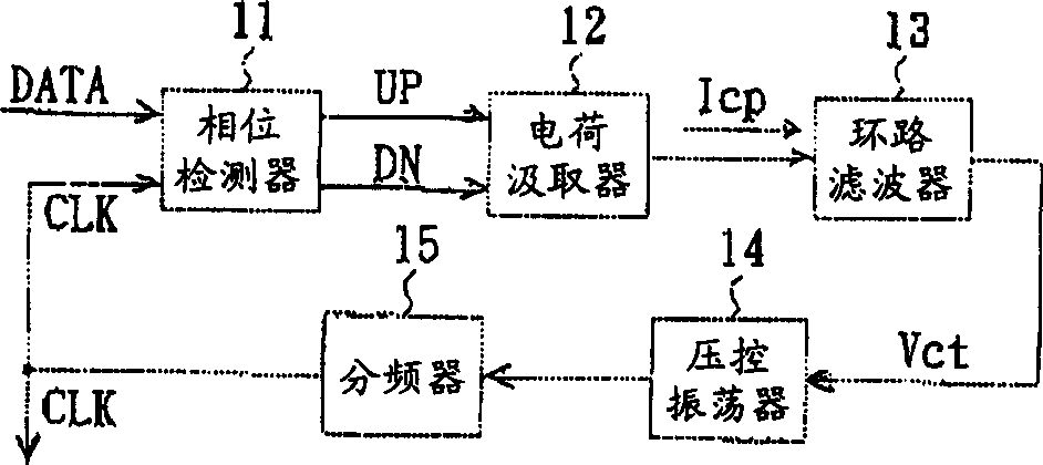
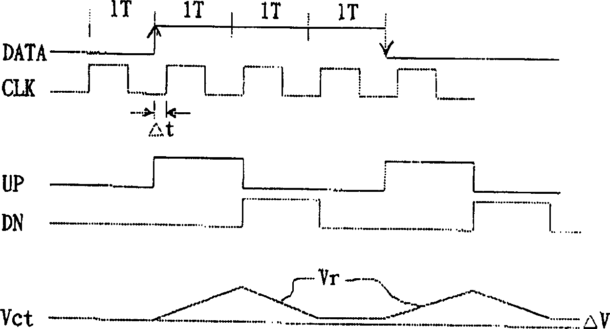
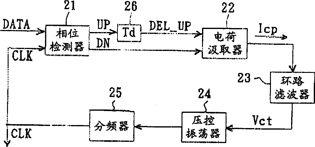
[0012] First, the reference signs in the drawings are explained: 2—clock recovery system, 21—phase detector, 22—charge extractor, 23—loop filter, 24—voltage controlled oscillator, 25— -frequency divider, 26--time delay component, UP--rising pulse, DN--falling pulse, DEL_UP--delayed rising pulse, DATA--input signal, CLK--clock signal, I CP -- current, V ct --Control voltage, Δt--phase difference, Td--delay time, Δv--voltage.

[0013] refer to image 3 Shown is a circuit block diagram of a preferred embodiment of the method and device for reducing phase jitter in the clock recovery system of the present invention, and the clock recovery system 2, as described above, basically includes phases connected in sequence to form a closed loop Detector 21, charge extractor 22, loop filter 23, voltage-controlled oscillator (VCO) 24 and a frequency divider 25, and clock recovery system 2 is for an input signal DATA input, in order to according to this input signal DATA A clock signal CL...


PUM


Abstract

The invention provides a method to reduce phase shake in clock recovering system and the equipment. The clock recovering system has a phase detector to detect the phase difference between an input signal and a clock signal output by a voltage controlled oscillator, generates a rising pulse and a descending pulse according to the phase difference, and uses the two pulses to generate a control voltage of the voltage controlled oscillator. It uses a time delay component to make the two pulses overlap in the time field, to eliminate the ripple generated on the control voltage, so as to prevent the clock signal from producing phase shake.

Description

technical field [0001] The invention relates to a method and device for reducing phase jitter in a clock recovery system, in particular to a method that can eliminate the ripple on the control voltage of a voltage-controlled oscillator to avoid phase jitter caused by too fast changes of the voltage-controlled oscillator method and device. Background technique [0002] Phase Locked Loop (Phase Locked Loop) is commonly used as frequency control, which can generally be used as frequency multiplier (Multiplier), demodulator (Demodulator), track tracking generator (Tracking Generator), clock recovery system (Clock Recovery Circuit) and other applications. Recently, there are optical disc media with high reproduction rate, such as CD-ROM, DVD, etc., and a clock recovery system is used to perform synchronous regeneration of data. Such as figure 1 As shown, a typical clock recovery system 1 includes a phase detector 11 , a charge extractor 12 , a loop filter 13 , a voltage contro...

Claims


Application Information

Patent Timeline
IPC IPC(8): H03L7/00H03L7/06H03L7/08
Inventor 徐哲祥陈志成
Owner MEDIATEK INC
Why Eureka
Try Eureka