Supercharge Your Innovation With Domain-Expert AI Agents!

Axial-flow blower

An axial flow fan, fan technology, applied in mechanical equipment, gas turbine devices, machines/engines, etc., can solve problems such as difficult to master and operate, poor work reliability, large test equipment, etc., and achieve uniform and equal axial force. The effect of equalizing and improving working conditions

Inactive Publication Date: 2004-04-07
SHENYANG LIMING AERO-ENGINE GROUP CORPORATION
View PDF0 Cites 7 Cited by
  • Summary
  • Abstract
  • Description
  • Claims
  • Application Information

AI Technical Summary

Problems solved by technology

[0002] In the field of gas turbine performance testing, the methods adopted by countries around the world are not the same. Germany and other countries use hydraulic dynamometers, American GE uses generator dynamometers, and Russia uses generator winding resistance wires to measure dynamometers. The common problems are: test The equipment is huge, large in size, heavy in weight, large in investment, and difficult to grasp and operate
It is the first to use the axial flow fan as the load to carry out the gas turbine performance test, which can overcome the above-mentioned problems. However, due to the structural limitations of the existing axial flow fans, the axial force they can bear is too small, the working reliability is poor, and the service life is short. These problems also exist in smelting blast and mine ventilation

Method used


Image

  • Axial-flow blower
  • Axial-flow blower
  • Axial-flow blower

Examples


Embodiment Construction

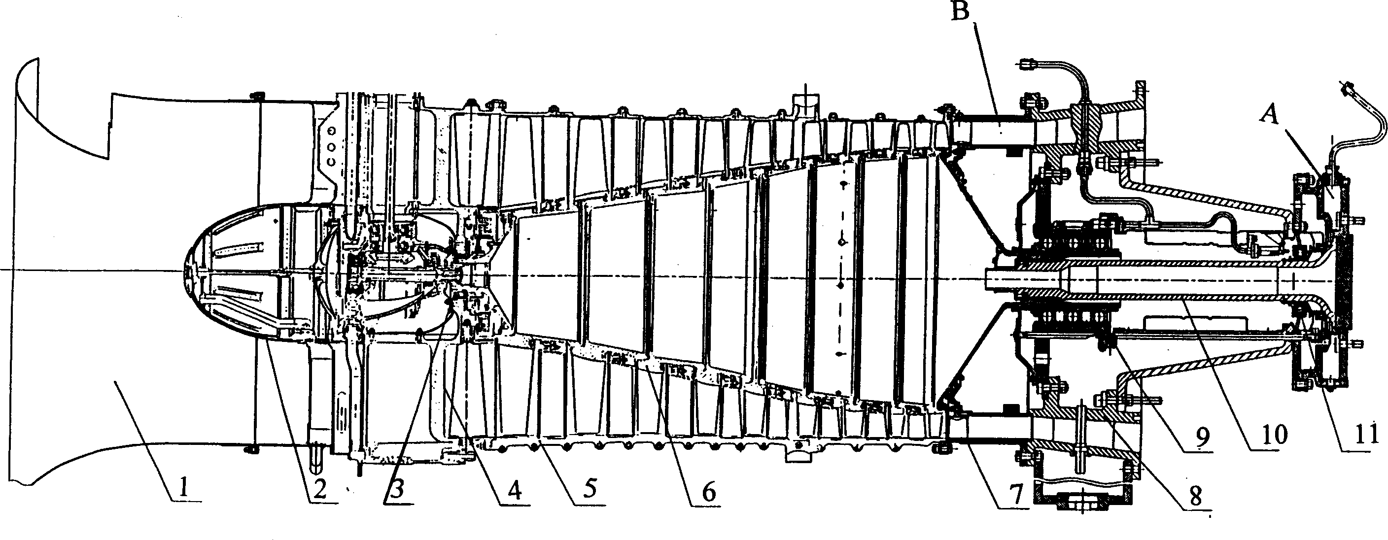
[0024] like figure 1 As shown, the axial flow fan of the present invention is composed of an air inlet assembly 1, an air intake device 2, a front support assembly 3, a front casing assembly 4, a middle casing assembly 5, a fan rotor assembly 6, a rear casing assembly 7, a rear bearing Force casing assembly 8, middle support assembly 9 (including middle support axial force bearing device), transmission shaft assembly 10, rear support assembly 11 (including rear support high pressure lead piece unloading device). The axial flow fan drive shaft assembly 10 is connected to the thrust plate 47 with the connecting bolts 58 (47, 58) through the thrust plate 47 fixed to it. Figure 9 Middle) is connected with the main shaft of the gas turbine through the coupling (not shown in the figure), the gas turbine drives the fan rotor assembly 6 to rotate at a high speed, the air enters the fan from the air inlet assembly 1, and the guide vanes on the air intake device 2 connect the rotor inl...


PUM


Abstract

The axial flow blower consists of intake channel, intake device, front casing, middle casing, back casing, front bearing, middle bearing, back bearing, rotor, drive shaft, back bearing casing and other parts. The middle baring assembly has three rows thrust ball bearings forming the middle axial bearing unit to bear the giant forward axial force the rotor assembly produces; and the back bearing assembly has sealing casing and thrust cavity to form booster cavity, introduces high pressure air the blower exhaust channel exhausts and constitutes the back bearing high pressure air guiding unloader. The thrust disc produces backwards axial force to balance most forward axial force of the blower rotor assembly. The combined function of these two devices makes the axial-flow blower capable of bearing giant axial force. The present invention is used in gas turbine and air system air source machine.

Description

Technical field [0001] The invention belongs to the field of fluid mechanical equipment, and particularly relates to a gas turbine test and an air system air source machine, which can be used for smelting blasting and mine ventilation, can bear a sufficiently large axial force, has good working reliability and is easy to use. Long life axial fan. Background technique [0002] In the field of gas turbine performance testing, the methods adopted by different countries in the world are different. Germany and other countries use hydraulic dynamometers, GE in the United States uses generator dynamometers, and Russia uses generator winding resistance wires to measure dynamometers. The common problems are: test The equipment is huge, large in size, heavy in weight, large in investment, and difficult to master and operate. The use of axial flow fans as the load to conduct gas turbine performance tests is the first initiative, which can overcome the above problems. However, due to t...

Claims


Application Information

Patent Timeline
IPC IPC(8): F02C3/06F04D29/32
Inventor 崔荣繁庞为阎成祥陈克杰王惠林宋乐民王敬松
Owner SHENYANG LIMING AERO-ENGINE GROUP CORPORATION
Features
  • R&D
  • Intellectual Property
  • Life Sciences
  • Materials
  • Tech Scout
  • Unparalleled Data Quality
  • Higher Quality Content
  • 60% Fewer Hallucinations
Learn More