
Method and apparatus for compensating dispersion for dispersion displacement optical fiber c waveband wave division signal transmission

A dispersion-shifted optical fiber and dispersion compensation technology, which is applied in the field of dispersion compensation, can solve the problems of large dispersion and reduce the performance-price ratio of DWDM systems, and achieve the effects of mature technology, low cost and good isolation

Inactive Publication Date: 2004-04-14
HUAWEI TECH CO LTD
View PDF0 Cites 2 Cited by
  • Summary
  • Abstract
  • Description
  • Claims
  • Application Information

AI Technical Summary

Problems solved by technology

However, in the above-mentioned G.653 optical fiber C-band wavelength division transmission scheme, although the dispersion value of the G.653 optical fiber is very small, if the transmission distance is long, it will also accumulate a large dispersion. If the dispersion value exceeds The dispersion tolerance of the receiver requires dispersion compensation. Since the red and blue bands are respectively on both sides of the zero dispersion wavelength of the G.653 fiber, the red band accumulates positive dispersion, while the blue band accumulates negative dispersion, so the red and blue bands The compensation method of the band is completely opposite, requiring a special G.653 dispersion compensation scheme
Due to the particularity of G.653 optical fiber, there is no dispersion compensation scheme for G.653 optical fiber C-band wavelength division transmission at present, which makes G.653 optical fiber C-band wavelength division DWDM signal can only be transmitted within a short distance, thus Seriously reduce the performance-price ratio of DWDM system

Method used


Image

  • Method and apparatus for compensating dispersion for dispersion displacement optical fiber c waveband wave division signal transmission
  • Method and apparatus for compensating dispersion for dispersion displacement optical fiber c waveband wave division signal transmission
  • Method and apparatus for compensating dispersion for dispersion displacement optical fiber c waveband wave division signal transmission

Examples


Embodiment Construction

[0033] In the current G.653 optical fiber C-band wavelength division transmission scheme, the wavelength used by the system can be divided into red wave band and blue wave band according to the zero dispersion wavelength 1550nm of G.653 optical fiber, and the wavelengths at both ends of the C-band should be as close as possible , so that a larger dispersion value can be obtained, so that the four-wave mixing FWM is smaller, so that the system has better performance. Since the red and blue bands are on both sides of the zero-dispersion wavelength of G.653 optical fiber, it is assumed that the signal transmission in the red band and the blue band conforms to the G.653 optical fiber standard recommended by the ITU Telecommunication Standardization Department (ITU-T). G.653 optical fiber has a dispersion coefficient of -3.0 to 2.8 ps / nm / km from 1535nm to 1560nm, so that the red wave band and the blue wave band will accumulate a large dispersion in the transmission distance, even ac...


PUM


Abstract

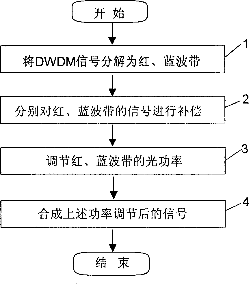
First, red blue-band wave separator is utilized to decompose signal of dense wavelength division multiplex (DWDM) into red band and blue band. Then, negative dispersion compensation module (-DCM) is utilized to compensate signal in red band, and positive dispersion compensation module (+DCM) is utilized to compensate signal in blue band. Finally, wave synthesizer for red and blue bands is utilized to compose compensated signals. Moreover, in order to keep balance for powers at output ends of wave synthesizer for red and blue bands, tonable optical attenuator can be utilized to adjust light power of red or blue band. Dispersion compensation module in low cost for G.652 optical fiber can be utilized as positive DCM or negative DCM in the invention. Thus, the device disclosed in the invention also will be more economic.

Description

technical field [0001] The invention relates to a dispersion compensation method and device in optical signal transmission, in particular to a dispersion compensation method and device in dispersion-shifted optical fiber (G.653 optical fiber) C-band wavelength division signal transmission. Background technique [0002] The dispersion value of single-wave transmission using G.653 optical fiber near the zero-dispersion wavelength of 1550nm is very small, and the accumulated dispersion of the system after long-distance transmission is also very small, and good transmission performance can be obtained without compensation. Therefore, this optical fiber has been widely used in many parts of the world. However, when this kind of fiber is used for dense wavelength division multiplexing (DWDM) wavelength division signal transmission, it is precisely because the dispersion value is very small that the serious four-wave mixing (FWM) effect will occur during DWDM wavelength division si...

Claims


Application Information

Patent Timeline
IPC IPC(8): G02B6/26G02B6/293G02F1/01
Inventor 钟开生马先
Owner HUAWEI TECH CO LTD
Learn More