Turbine

A technology of turbines and turbine stages, used in gas turbine installations, cooling of turbine/propulsion installations, mechanical equipment, etc., to solve problems such as wear, partial overheating of rotors, and overheating of the area from the compressor outlet to the turbine.

Inactive Publication Date: 2004-05-26
SIEMENS AG
View PDF2 Cites 6 Cited by
  • Summary
  • Abstract
  • Description
  • Claims
  • Application Information

AI Technical Summary

Problems solved by technology

[0006] Although EP 0447886 A1 is not concerned with water cooling and thus without the attendant corrosion of the turbine, there is however the risk of the rotor being partially overheated, or rather compressed, when pressure increases inside the compressor due to ambient temperature and ambient pressure changes There is a risk of overheating in the area of ​​the engine outlet to the turbine
This overheating of the rotor combined with undesired thermal expansion and / or mechanical stress leads to wear

Method used


Image

  • Turbine
  • Turbine

Examples


Embodiment Construction

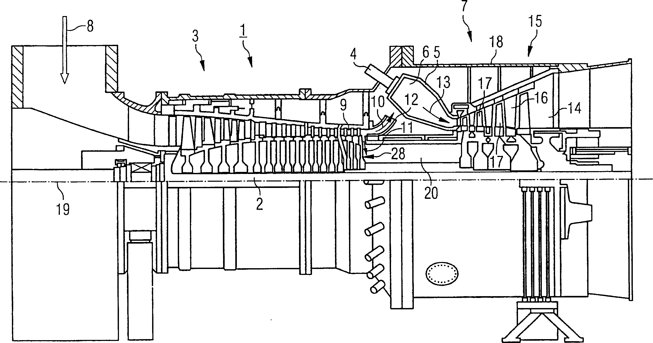
[0024] figure 1 is a partial longitudinal section through a turbine 1 designed as a stationary gas turbine with a rotor 2, a compressor 3, a combustor 4, an annular combustion chamber 5 with a combustion chamber 6 and a turbine section 7.

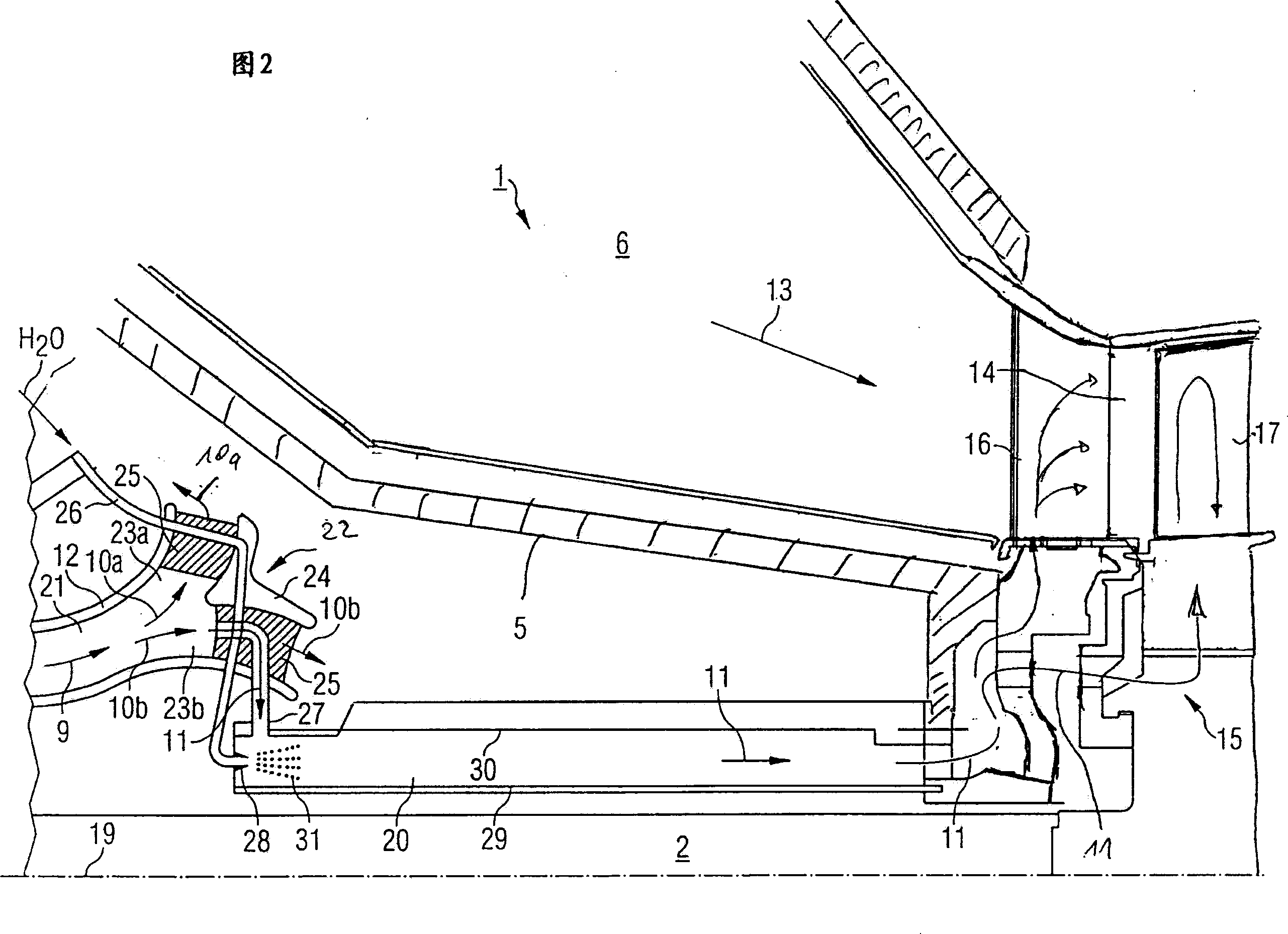
[0025] When the turbine 1 is in operation, the compressor 3 sucks in air 8 at one end, which is already prepared as compressed air 9 at the other end. The air 9 is then divided into a mass air flow 10 and a cooling air flow 11 . The cooling air flow 11 is used to cool the turbine section 7 and the rotor 3 , while the air mass flow 10 is used initially for cooling the annular combustion chamber 5 and then for combustion. For this purpose, after discharge from the compressor 3 , the air mass flow 10 is redirected by the diffuser 12 in the direction of the annular combustion chamber 5 and from there is directed further to the burner 4 . The air mass flow 10 is then mixed with fuel in the burner 4 , and the fuel is thus combusted in the comb...


PUM


Abstract

Turbine comprises a rotatably mounted rotational-symmetrical rotor (2) having rotating blades (17) on its outer periphery toward which a working medium is directed, a cooling fluid produced by a compressor for cooling the guide blades (16) interacting with the rotating blades, and a channel connected to the rotor for cooling fluid. The cooling fluid in the channel is cooled by evaporating a liquid. An Independent claim is also included for a gas turbine (1) comprising the above turbine. Preferred Features: The channel runs along the rotor and is connected to the rotor so that the rotor is also cooled by the cooling fluid. The channel is an annular channel (20) formed coaxially to the rotor and having an inner side formed by the rotor surface.

Description

technical field [0001] The invention relates to a turbomachine, especially a gas turbine. Background technique [0002] A cooled gas turbine is known from German patent document DE 2852057, in which the cooling air extracted from the compressor is cooled by means of water spraying. For this purpose the gas turbine has a water line which terminates in a spray chamber. The spray chamber is bounded radially on the one hand by the rotor and on the other hand by a fixed wall surrounding the rotor. The injected water is atomized into fine water droplets in the spray chamber, where these water droplets are only partially evaporated. The rotor is cooled during this process. The cooled cooling air then flows further to the working blades of the first few turbine stages. The water droplets remaining in the cooling air are now evaporated in the rotor blades in order to keep the cooling air temperature low there. [0003] The water droplets cause corrosion and wear on their way in ...

Claims


Application Information

Patent Timeline
Patent Type & Authority Applications(China)
IPC IPC(8): F02C7/16F01D5/08F02C7/18F23R3/04
CPCF01D5/084F05D2260/212F05B2260/212F02C7/185F01D5/085F05D2260/232F05B2260/232
Inventor 彼得·蒂曼
Owner SIEMENS AG
Why Eureka
Try Eureka