
Loading method for ensuring to load programmable part reliably

A reliable and device-based technology, applied in the field of delayed loading, can solve problems such as negative impact on chip life and reliability, chip damage, etc., to avoid side effects and ensure correctness and reliability.

Inactive Publication Date: 2004-05-26
ZTE CORP
View PDF0 Cites 7 Cited by
  • Summary
  • Abstract
  • Description
  • Claims
  • Application Information

AI Technical Summary

Problems solved by technology

One is to use a fast-start power supply, and then use the delay of the FPGA itself. This solution requires a very short time for the power supply to rise from 0V to 3.3V, but it brings two problems at the same time. One is to limit the choice of power supply. The second is the negative impact of fast power-on on the life and reliability of the chip
The second solution is to add a capacitor to the detection pin of the FPGA. This solution can avoid the defects of the previous solution. However, due to the energy storage effect of the capacitor, when the device is powered on quickly after power-off, it may also cause damage to the device when it fails to load. chip damage
In this way, there is a congenital deficiency in reliability

Method used


Image

  • Loading method for ensuring to load programmable part reliably
  • Loading method for ensuring to load programmable part reliably
  • Loading method for ensuring to load programmable part reliably

Examples


Embodiment Construction

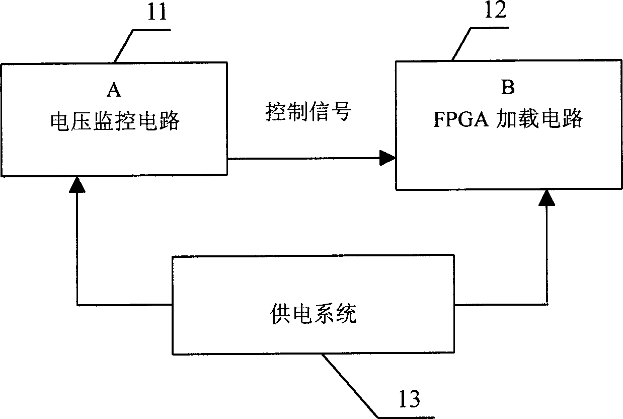
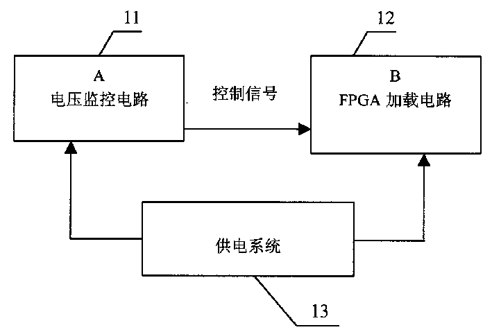
[0013] The invention utilizes the voltage detection function of the voltage monitoring chip to realize accurate monitoring of the voltage, thereby obtaining a reliable time to start the loading action of the FPGA. This solution consists of the following two parts: a voltage monitoring circuit 11 and an FPGA loading circuit 12 . The relationship between the two see figure 1 . The power supply circuit 13 supplies power to both, which will be described in detail below.

[0014] 1. Voltage monitoring circuit

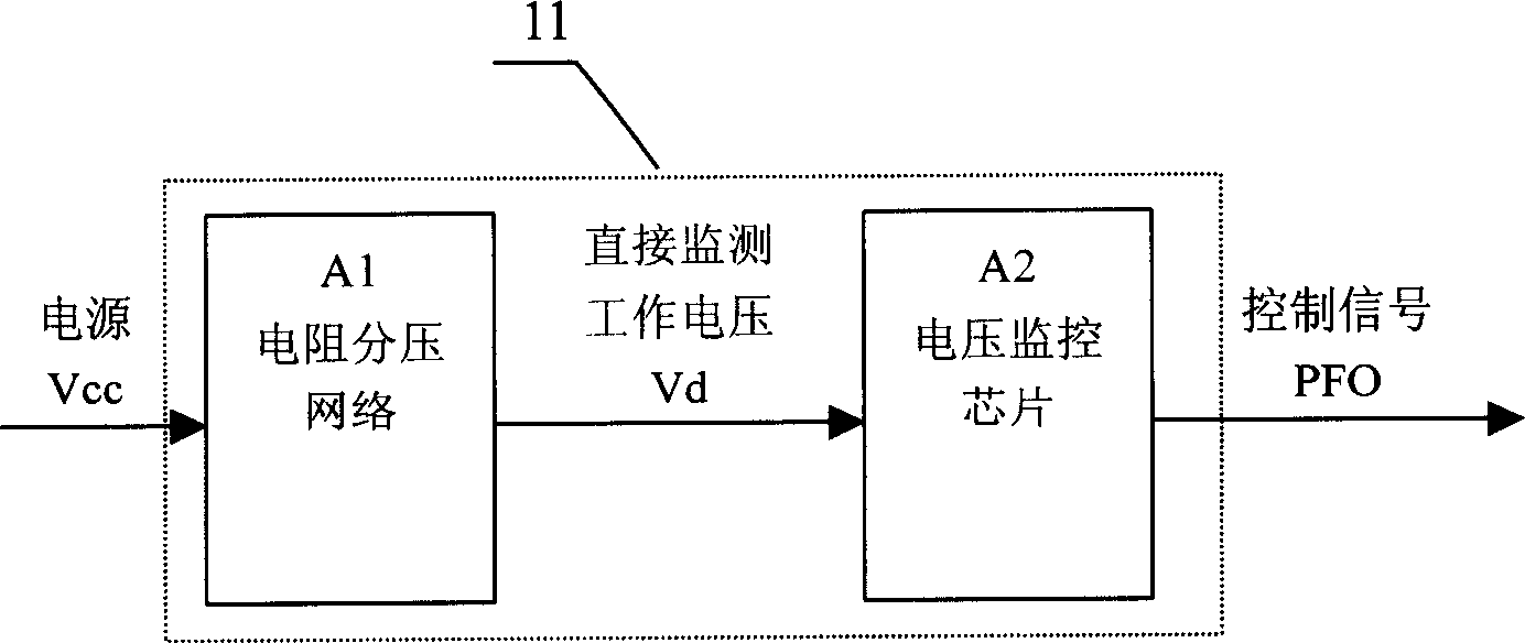
[0015] Voltage monitoring circuits can also be subdivided into figure 2 The two parts shown.

[0016] A2 is the voltage monitoring chip part of this circuit. In addition to monitoring the power supply voltage, usually this type of chip can also provide a PFI pin to monitor a specific voltage value Vd. When the voltage value Vd on the PFI pin is greater than When Vpfi (Vpfi is the threshold voltage of the voltage monitoring circuit), the corresponding output pin PFO out...


PUM


Abstract

The invention relates to watch dog / voltage monitoring technique and application method of FPGA. The method includes following steps. (1) After power up, voltage-monitoring chip starts work to monitor operating voltage Vd first. (2) Whether Vd is larger than threshold Vpfi of the chip is determined in order to meet condition for FPGA to start configuration. (3) If Vd>Vpfi, then the control signal PFO output from the chip is high, configuration procedure is started by FPGA; if Vd is less than or equal or Vpfi, the loading configuration procedure is prohibited. A divider circuit is added in front of the voltage-monitoring chip. Resistance potential-divider network A1 obtains voltage division, which is also as input of PFI, of voltage Vcc to be monitored. Sharing function of voltage-monitoring circuit detects the time when single board / device enters into normal state in order to guarantee that FPGA completes loading under correct state.

Description

technical field [0001] The invention relates to a method for realizing delayed loading of FPGA by using a watchdog / voltage monitoring circuit, and mainly relates to a watchdog / voltage monitoring technology in the field of electronic technology and an application method of FPGA. Background technique: [0002] In FPGA applications, an additional PROM is usually required to store the data required for FPGA loading. This loading process is usually completed automatically when the board or device is powered on. Because this loading process is executed after judging the power supply voltage through a certain pin of the FPGA chip, and the FPGA is a pure digital chip, it cannot detect the analog quantity. In other words, as long as the voltage of the detection pin is judged to be high , the FPGA loading process begins, and for TTL signals, a voltage exceeding 1.7V will be judged as a high level. Under such conditions, it may happen that the FPGA starts to load before the power supp...

Claims


Application Information

Patent Timeline
Patent Type & Authority Applications(China)
IPC IPC(8): G06F1/28
Inventor 杜广杨松郭向东
Owner ZTE CORP
Learn More