Supercharge Your Innovation With Domain-Expert AI Agents!

Air flow system for microwave oven

A technology of air flow and microwave oven, which is applied in the direction of household stove/stove, household heating, lighting and heating equipment, etc. It can solve the problems of complex flow channels and increase product cost, so as to improve air flow velocity, save costs and achieve good cooling effect Effect

Inactive Publication Date: 2004-06-09
LG ELECTRONICS (TIANJIN) APPLIANCES CO LTD
View PDF0 Cites 6 Cited by
  • Summary
  • Abstract
  • Description
  • Claims
  • Application Information

AI Technical Summary

Problems solved by technology

[0016] That is to say, the flow channel of air includes a plurality of blower fans and blower motors such as a cooling motor positioned on one side of the upper end, a cooling fan in the electric control room, and a heater cooling fan for cooling the heater. Complicated, and requires a lot of expense to install each part, which increases the product cost

Method used


Image

  • Air flow system for microwave oven
  • Air flow system for microwave oven
  • Air flow system for microwave oven

Examples


Embodiment Construction

[0038] The structure of the embodiment of the air flow system of the microwave oven according to the present invention will be described in detail below with reference to the accompanying drawings.

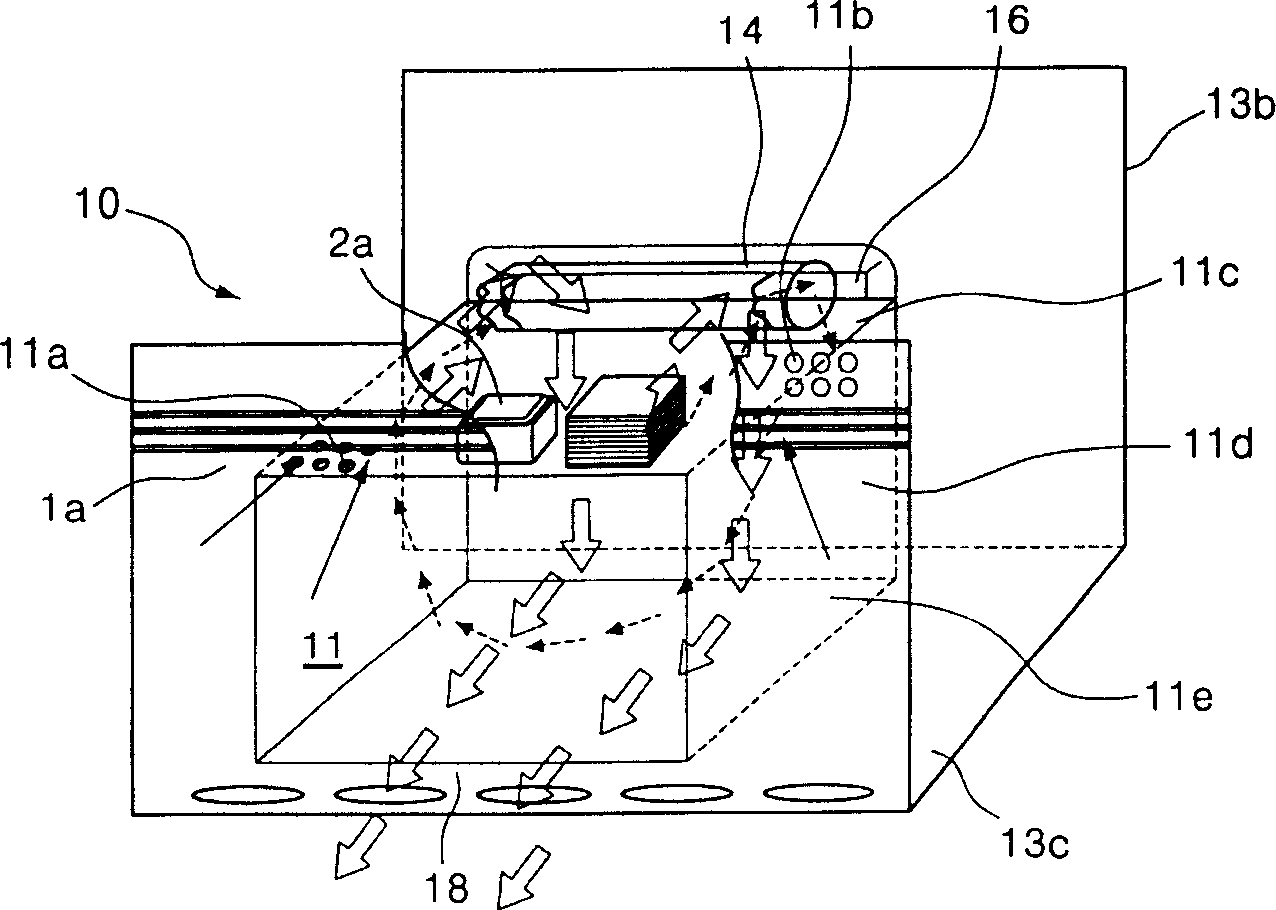
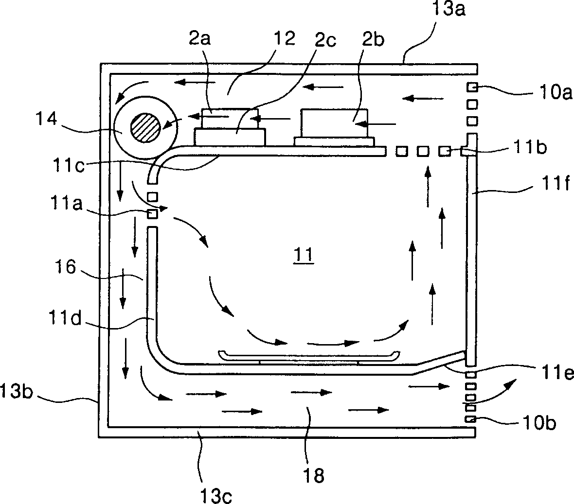
[0039] figure 2 Shows the oblique view of the microwave oven of the present invention, image 3 A side view of a microwave oven of the present invention is shown.

[0040] figure 2 and image 3 In the shown embodiment, the electric control room 12 of the microwave oven is located between the upper surface 11c of the heating chamber of the microwave oven and the upper surface 13a of the outer casing. The electric control room 12 includes the following structures: a magnetron 2a, a high voltage transformer 2b and a waveguide 2c. The magnetron 2a generates microwaves; the high-voltage transformer 2b generates high-voltage current required for the magnetron 2a to generate microwaves; the waveguide 2c guides the microwaves generated by the magnetron 2a into the heating chamber. In...


PUM


Abstract

The present invention relates to an air flowing system for built-in type microwave oven, and its structure includes: air suction grate placed on the upper end portion of front surface of microwave oven for sucking exterior air; vertical hexahedral heating chamber in which the object to be heated can be placed; air discharge motor mounted on the rear end of upper portion of the heating chamber for sucking exterior air by means of air suction grate; electric control chamber component placed in the electric control chamber positioned in inside of air suction grate and in the upper portion of ehating chamber; back air flowing channel formed between back surface plate of heating chamber device and back surface of the heating chamber; bottom surface air flowing channel formed between bottom plate of microwave oven and bottom surface of heating chamber; and air discharge grate mounted in lower end of front surface of microwave oven.

Description

technical field [0001] The invention relates to an air flow (AIRFLOW) system of a microwave oven. In particular, it relates to an air flow system of a microwave oven with the following effects: the cooling effect can be improved, the structure of the cooling device can be simplified, and the product cost can be reduced. Background technique [0002] A microwave oven is a device that generates microwaves (MICROWAVE) from a supplied electric current, and irradiates an object to be heated with the microwaves to heat them. [0003] figure 1 Front cutaway view showing the components of a microwave oven. [0004] The above-mentioned microwave oven heats the object to be heated mainly by irradiating microwaves generated by the magnetron (MAGNETRON) 1 installed in the electric control chamber 7 to the inside of the heating chamber. The above-mentioned microwaves are irradiated to the inside of the heating chamber through the antenna (ANTENNA) and the waveguide (WAVEGUIDE). In or...

Claims


Application Information

Patent Timeline
IPC IPC(8): F24C7/02
Inventor 吴圭镐
Owner LG ELECTRONICS (TIANJIN) APPLIANCES CO LTD
Features
  • R&D
  • Intellectual Property
  • Life Sciences
  • Materials
  • Tech Scout
  • Unparalleled Data Quality
  • Higher Quality Content
  • 60% Fewer Hallucinations
Learn More