
Ion generator and air conditioning apparauts

A technology for ion generators and generating devices, which can be used in air-conditioning systems, air quality improvement, lighting and heating equipment, etc., and can solve the problems of reducing the relaxation effect of negative ions

Inactive Publication Date: 2004-06-09
SHARP KK
View PDF3 Cites 13 Cited by
  • Summary
  • Abstract
  • Description
  • Claims
  • Application Information

AI Technical Summary

Problems solved by technology

[0011] However, positive ions have the property of causing people to feel oppressive. Therefore, if positive ions and negative ions are generated, the relaxation effect of negative ions will be reduced and offset. Therefore, it is necessary to switch the operating mode according to the application.

Method used


Image

  • Ion generator and air conditioning apparauts
  • Ion generator and air conditioning apparauts
  • Ion generator and air conditioning apparauts

Examples


no. 1 example

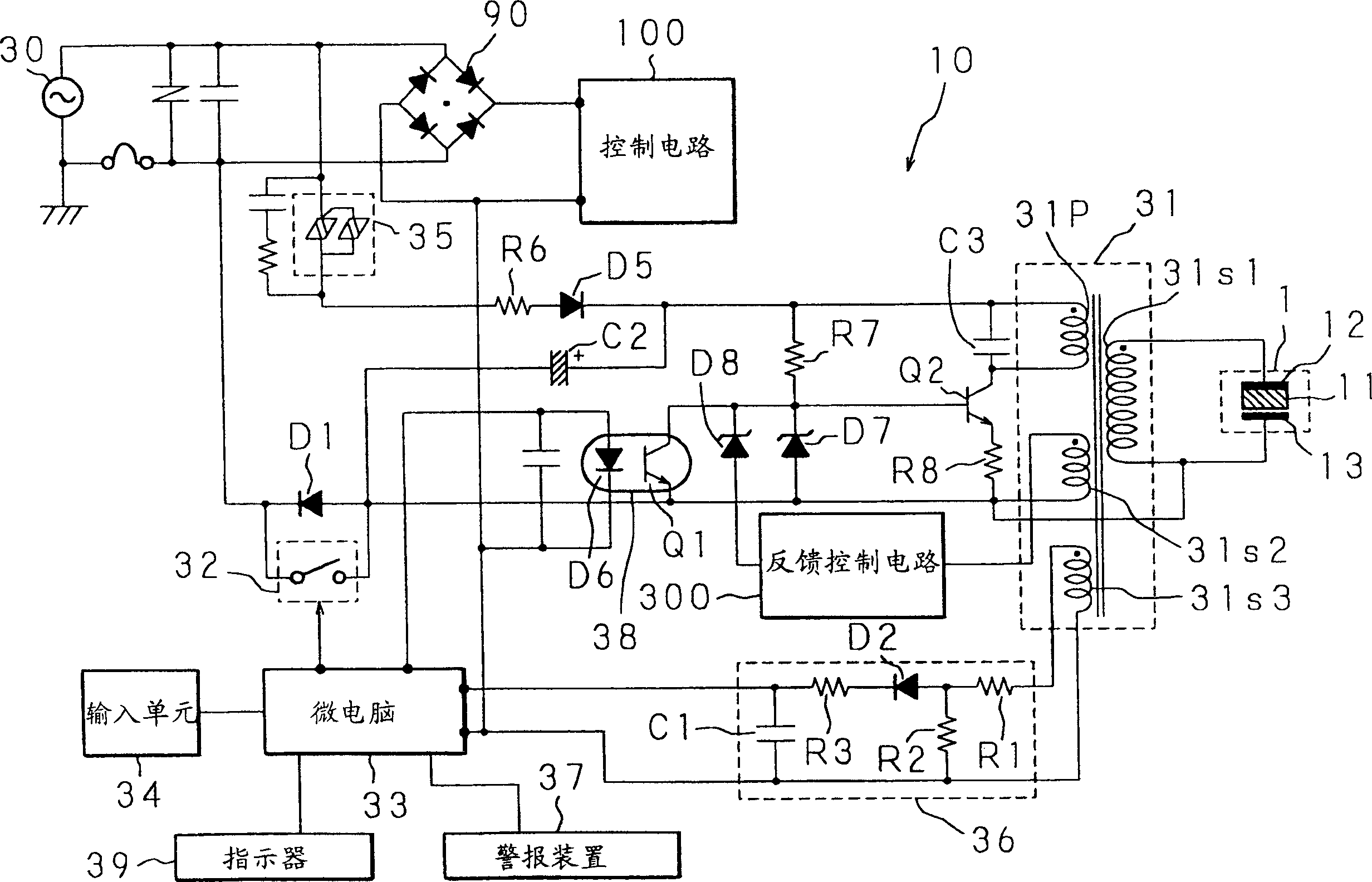
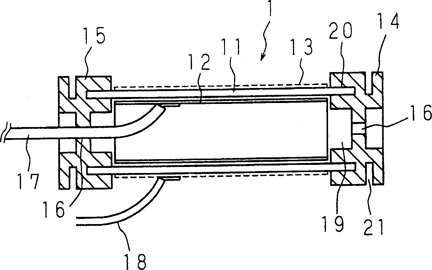
[0053] see figure 1 , 2 , the following description will explain the first embodiment of the ion generator of the present invention.

[0054] figure 1 It is a circuit diagram showing the circuit structure of an ion generator 10 including a rectifier 90 connected to a commercial power supply 30 and a control circuit connected to the output terminal of the rectifier 90 . A control circuit 100 is a control circuit of the air conditioner described later.

[0055] Furthermore, the ion generator 10 includes an ion generating electrode main body 1, a switching transformer 31, a relay 32, a microcomputer 33, an input unit 34 of the microcomputer 33, an SSR 35 (solid state relay), a fault detection circuit 36, An alarm device 37 , an optical coupler 38 , an indicator 39 , and a feedback control circuit 300 .

[0056] The switching transformer 31 includes a primary winding 31p, and secondary windings 31s1, 31s2, 31s3. The secondary winding 31s1 is used to apply an AC high voltage to...

no. 2 example

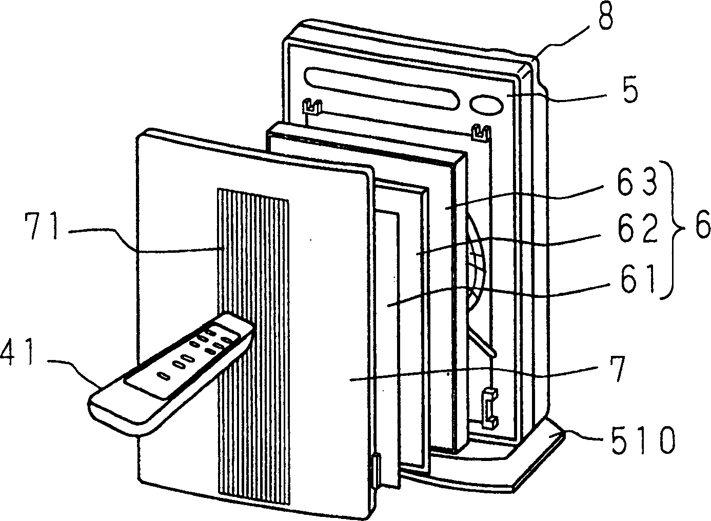
[0077] Next, the following description will illustrate the integration of an ion generator 10 into an air conditioner.

[0078] Figure 3 to Figure 12 Shown is an air cleaner as an example of an air conditioner, and the air cleaner includes a main body 5 having a flat box shape as if standing vertically, a base 510 for supporting the main body 5, and a base 510 attached to The front cover 7 on one side of the main body 5 (in this example, the front side), and a gap is provided between the front cover 7 and the main body 5 . The front face of the main body 5 is gently curved to have a convex center when viewed from above, and the front cover 7 is also curved to have a correspondingly convex center when viewed from above. An air inlet 71 formed by arranging a plurality of vertically long slits in parallel is formed in the center of the front cover 7, and the gap between the four edges of the front cover 7 and the main body 5 functions as a side air inlet 72 ( see Figure 6 )....


PUM


Abstract

A switching transformer applies an alternating high voltage across an internal electrode and an external electrode which face each other with a glass tube as a dielectric body between them. The anode side of a diode is connected to the external electrode which is not a voltage supply side electrode, while the cathode side is grounded. When a relay connected to both the terminals of the diode is turned on, substantially equal amounts of positive ions and negative ions are generated, and a bacteria removal / disinfection effect can be obtained by emitting these positive ions and negative ions into the air. When the relay is turned off, a relatively small amount of positive ions and a relatively large amount of negative ions are generated, and a relaxation effect given by negative ions can be obtained by emitting these positive ions and negative ions into the air.

Description

technical field [0001] The present invention is about an ion generator that generates ions in the air, and an air-conditioning device combined with this ion generator. Please note that an air-conditioning device refers to all devices that generate any desired atmospheric environment by changing the physical properties of the air. An example of this device Includes air conditioners, air filters, dehumidifiers, humidifiers, and fan heaters. Refrigerators also belong to the field of air-conditioning devices within the scope of the present invention. Background technique [0002] Indoor air can be polluted by many substances, such as dust, cigarette smoke, and carbon dioxide emitted by breathing. In recent years, as airtightness in a room has increased, pollutants are likely to remain indoors, and ventilation thus needs to be performed at a higher rate. However, in buildings located in areas of severe air pollution, and in the homes and offices of people suffering from hay fev...

Claims


Application Information

Patent Timeline
Patent Type & Authority Applications(China)
IPC IPC(8): A61L9/22F24F3/16H01T23/00
CPCH01T23/00A61L9/22F24F3/166F24F2003/1682F24F8/192F24F8/30
Inventor 世古口美德古桥宪治守川守
Owner SHARP KK
Learn More