
Organic electroluminescent diode display element

A technology of electroluminescence and display components, which is applied in the direction of electrical components, electroluminescence light sources, electric light sources, etc., and can solve the problems of increased manufacturing process costs, film layer stress matching, and expensive investment in sputtering equipment

Inactive Publication Date: 2004-06-23
RITDISPLAY
View PDF0 Cites 5 Cited by
  • Summary
  • Abstract
  • Description
  • Claims
  • Application Information

AI Technical Summary

Problems solved by technology

[0010] 1. The organic light-emitting layer and the optical interference layer must be plated on different machines
[0011] 2. The result of coating with different machines will cause the problem of stress matching between the film layers, which will lead to a decrease in the yield and an increase in the cost of the manufacturing process
[0013] 4. Since the optical interference layer is plated by sputtering, the investment in sputtering equipment (machine) is relatively expensive

Method used


Image

  • Organic electroluminescent diode display element
  • Organic electroluminescent diode display element
  • Organic electroluminescent diode display element

Examples


Embodiment Construction

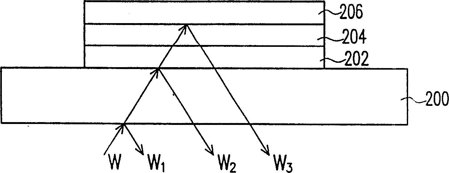
[0035] image 3 Shown is a schematic diagram of the reflection of external light in an organic electroluminescent diode display element. Please refer to image 3 The organic electroluminescent diode display element is mainly composed of a transparent substrate 200 , a plurality of strip-shaped transparent anodes 202 , an organic functional layer 204 and a plurality of strip-shaped metal cathodes 206 . Among them, the refractive index n of the organic functional layer 204 1 and the refractive index n of the transparent anode 202 2 very close, while the refractive index n of the organic functional layer 204 1 For example, greater than the refractive index n of the transparent substrate 200 3 , where n 1 About 1.7 or so, n 2 is approximately between 1.8 and 2.0, while n 3 is about 1.5, and n 3 Greater than the refractive index of outside air (≈1).

[0036] The light in the organic electroluminescent display element is generated by the organic functional layer 204 . Altho...


PUM


Abstract

The organic electroluminescent diode display element consists of mainly one transparent base board, several anodes, one organic functional layer, one light absorption layer and several cathodes. The anodes are configured on the transparent base board, the organic functional layer configured on the transparent base board covers the anodes, the light absorption layer is configured on the organic functional layer, and the cathodes are configured on the light absorption layer. The light absorption layer is utilized in improving the reflection to outer light and further increasing the contrast of the organic electroluminescent diode display element.

Description

technical field [0001] The present invention relates to an organic electro-excited light-emitting diode display element, and in particular, to an organic electro-excited light-emitting diode display element having a light absorbing layer. Background technique [0002] The communication industry has become a mainstream industry today, especially portable communication products are the focus of development, and flat panel displays are the communication interface between humans and machines, so it is particularly important. The technologies currently used in flat-panel displays mainly include the following: Plasma Display Panel (PDP), Liquid Crystal Display (LCD), Inorganic Electro-luminescent Display (Electro-luminescent Display), Light Emitting Diode (Light Emitting Diode) , LED), vacuum fluorescent display (Vacuum Fluorescent Display), field emission display (Field Emission Display, FED) and electrochromic display (Electro-chromicDisplay) and so on. However, compared with o...

Claims


Application Information

Patent Timeline
IPC IPC(8): G09F9/30H01L27/15H01L51/50H05B33/00
Inventor 李勇志廖启智李君浩张美濙
Owner RITDISPLAY
Learn More