

Particle for displaying device, image displaying medium and imager
A display device, image display technology, applied in identification devices, static indicators, instruments, etc., can solve the problems of image imbalance, image uniformity reduction, density difference, etc.
- Summary
- Abstract
- Description
- Claims
- Application Information
AI Technical Summary
Problems solved by technology
Method used
Image

Examples
no. 2 example -
[0119] The second embodiment of the present invention will be described in detail below in conjunction with the accompanying drawings.
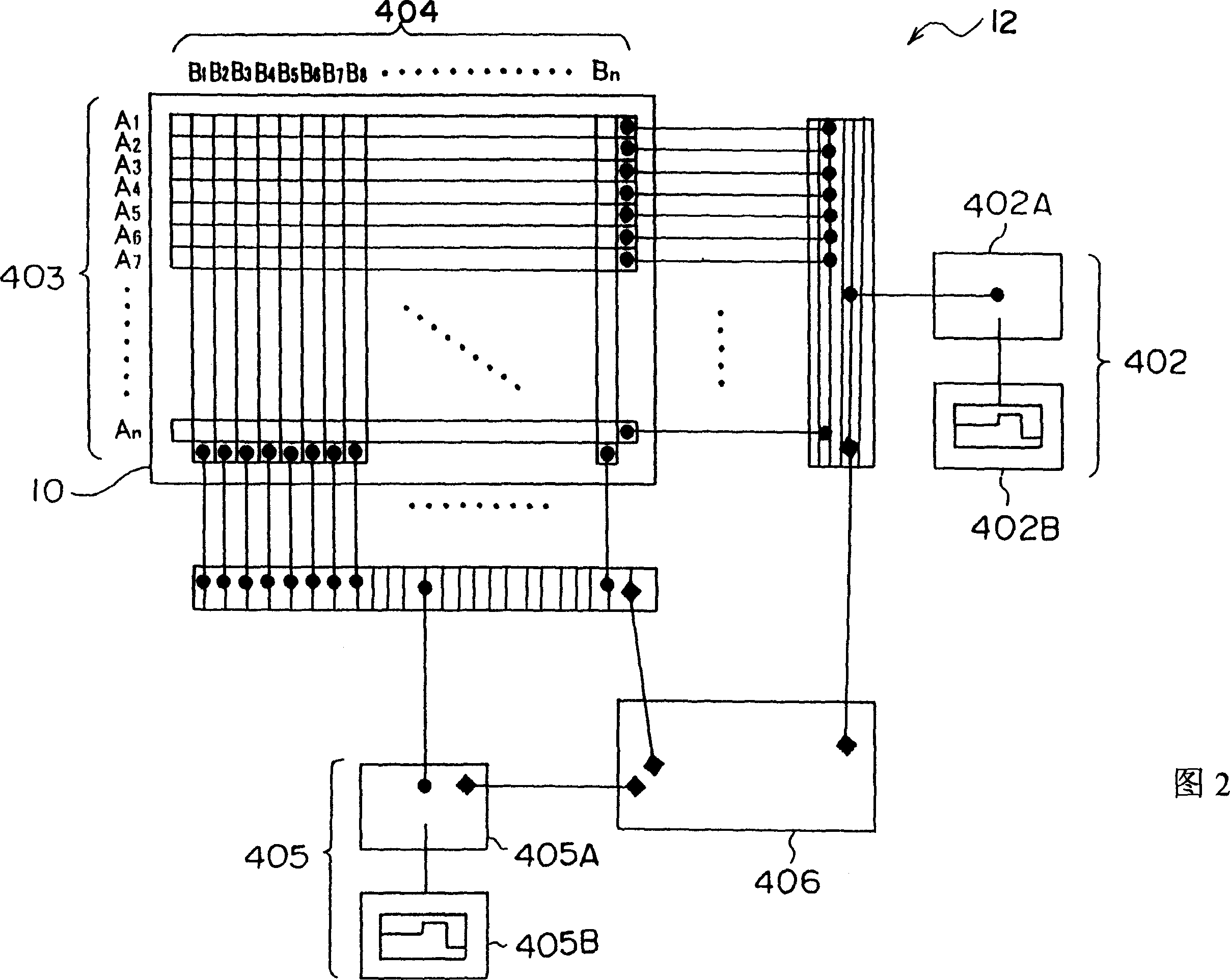
[0120] Fig. 2 is a schematic structural view showing another example (second embodiment) of the image forming apparatus of the present invention, showing an image forming process of forming an image on an image display medium 10 with a simple matrix. device12.
[0121] Electrodes 403An and 404Bn (wherein, n is a positive number) are arranged on a plane parallel to the image display medium 10 in which a plurality of groups of display particles (not shown) different in charging performance from each other are sealed. ) to form a simple matrix structure. The electrode 403An is connected to the power source 405A of the electric field generating device 405 composed of the waveform forming device 405B and the power source 405A, and the electrode 404Bn is connected to the power source 402A of the electric field generating device 402 composed of the...
no. 3 example -
[0127] The third embodiment of the present invention will be described in detail below with reference to the accompanying drawings. Figure 6 is a schematic configuration diagram showing another example (third embodiment) of the image forming apparatus of the present invention. Specifically, the figure shows an image forming apparatus using printed electrodes.
[0128] Figure 6 The image forming apparatus 12 shown includes: a printed electrode 11; and an opposing electrode 26, which is arranged opposite to the printed electrode 11 and grounded.
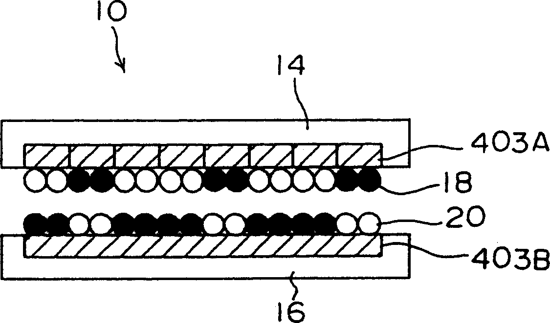
[0129] The image display medium 10 can move between the printed electrode 11 and the opposite electrode 26 in the direction indicated by the arrow B. As shown in FIG. The image display medium 10 is composed of a pair of substrates (a display substrate 14 and a non-display substrate 16); and display particles 18 and 20 are sealed between the pair of substrates. When the image display medium 10 is moved in the direction indicated by...
no. 4 example
[0146] The fourth embodiment of the present invention will be described in detail below with reference to the accompanying drawings. Figure 9 A schematic structure of another example (fourth embodiment) of the image forming apparatus of the present invention is shown. Figure 9 An image forming apparatus using a latent electrostatic image carrier is shown in .
[0147] Figure 9 The shown image forming apparatus 12 is mainly composed of the following components: a drum-shaped latent electrostatic image carrier 24 that can rotate in the direction shown by arrow A; a drum-shaped opposite electrode 26; and an image display medium 10 in which display particles are sealed between a pair of substrates, the image display medium 10 being movable in the direction indicated by arrow B between the latent electrostatic image carrier 24 and the opposite electrode 26 .
[0148] The charging device 80 is positioned at the periphery of the latent electrostatic image carrier 24 such that t...
PUM
| Property | Measurement | Unit |
|---|---|---|
| diameter | aaaaa | aaaaa |
| diameter | aaaaa | aaaaa |
| particle size | aaaaa | aaaaa |
Abstract
Description
Claims
Application Information