Dobby loom and loom mounted with said dobby loom

A technology for dobby machines and looms, applied in the field of dobby machines, can solve the problems of high force, bending or breaking of large-diameter rods, expensive materials, etc., to achieve effective force transmission, loose manufacturing tolerances, and cheap materials. Effect

Active Publication Date: 2004-07-14
STAUBLI HANGZHOU PRECISION MACHINERY ELECTRONICS CO LTD
View PDF1 Cites 2 Cited by
  • Summary
  • Abstract
  • Description
  • Claims
  • Application Information

AI Technical Summary

Problems solved by technology

This leads to higher forces in these rods and requires the use of materials with special mechanical properties whose machining must be carried out with high precision and are therefore more expensive
Given the large number of sharp accelerations they are subjected to, the large diameter rods may bend or break, which reduces the reliability of looms equipped with this dobby
Finally, a large diameter roller bearing had to be mounted on this rod at high cost

Method used


Image

  • Dobby loom and loom mounted with said dobby loom
  • Dobby loom and loom mounted with said dobby loom
  • Dobby loom and loom mounted with said dobby loom

Examples


Embodiment Construction

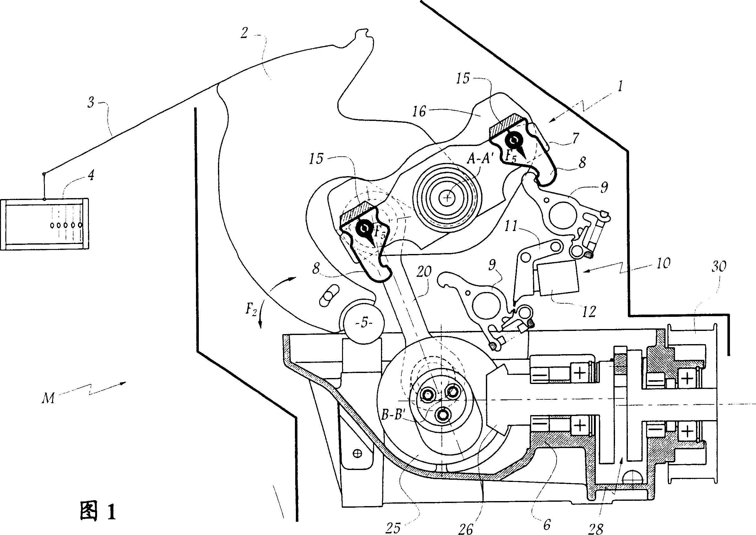
[0019] Referring now to the drawings, the dobby 1 shown in FIGS. The swing bar 2 is connected to a heald frame 4 of a loom M via a drawing cable 3 . The lever 2 is mounted to pivot about an axis 5 fixed relative to the frame 6 of the dobby 1 . arrow F 2 Indicates the rocking motion of rod 2.

[0020] The rod 2 is equipped with a double rocking rod 7 on which are articulated for selective control with a rocking rod 11 (rocking rod) belonging to a threading device 10 and interacting with an electromagnet 12. Keep hook 8 engaged with hook 9.

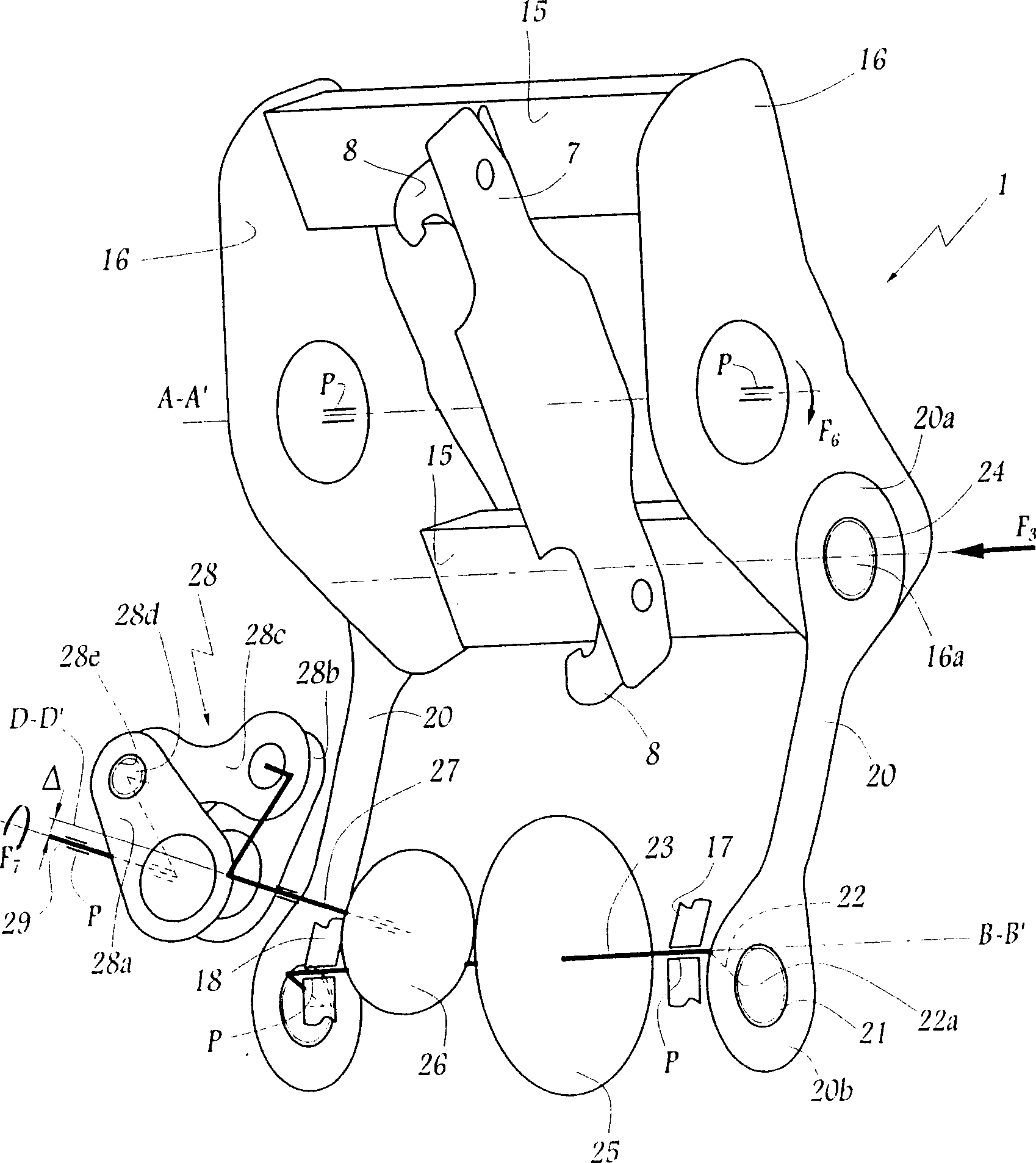
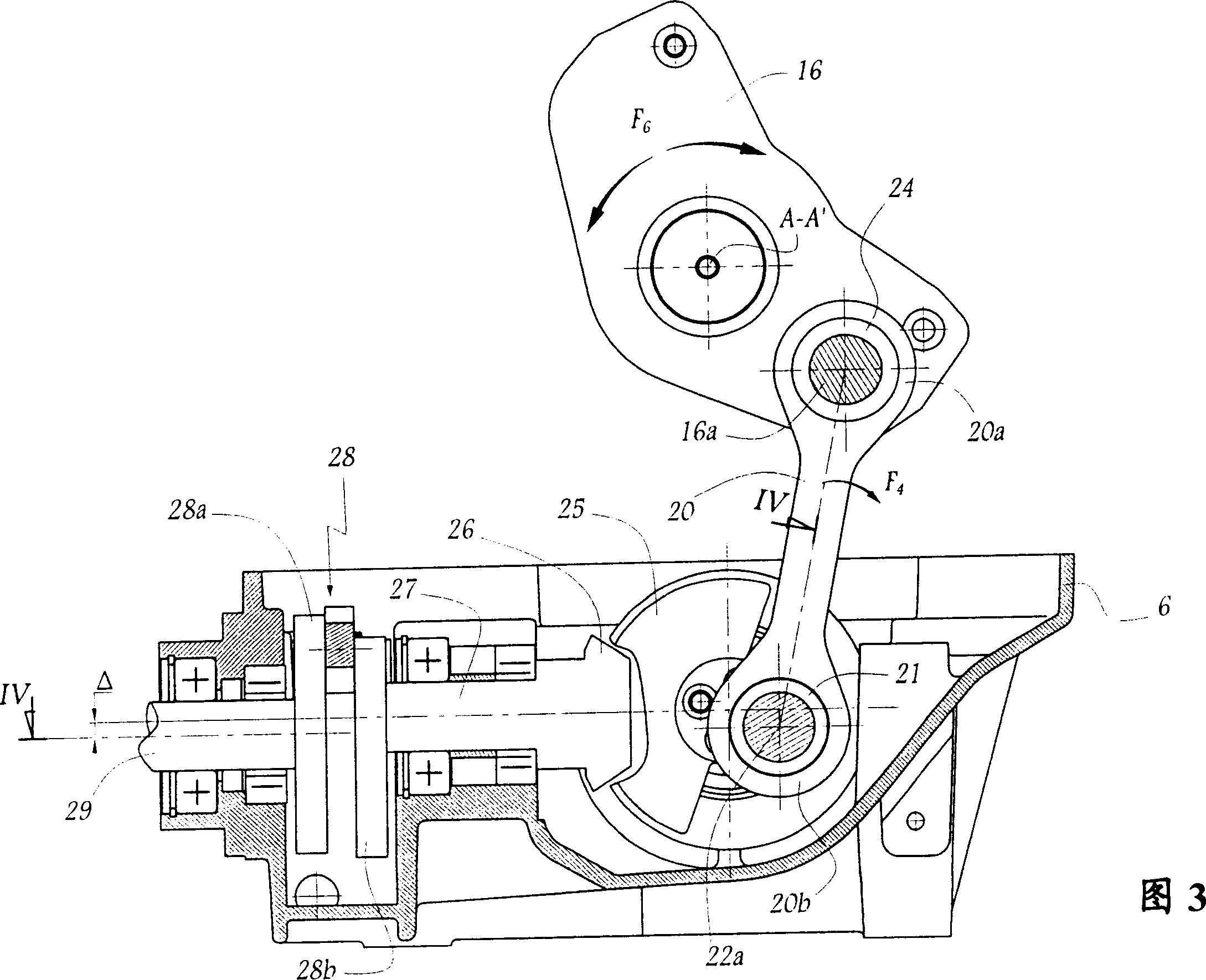
[0021] In order to pivot the double rocker 7 interacting with the rods 2 about an axis A-A' fixed relative to the frame 6, between the two drives 16 there is supported a pusher element 15 extending therebetween.

[0022] In this way, following the pivotal movement of the lever 7, one or the other of the movable hooks 8 can be held by one of the hooks 9, while the lever 2 is held in position near the dead center of its stroke. In the op...


PUM


Abstract

The loom dobby (1) consists of oscillating levers linked kinematically to a heddle frame, each lever being equipped with a balance arm (7) with hooks (8) and actuated by pushers (15) supported by drivers (16). Each driver is pivoted by an arm (20) connected to a crank (22) on the end of a shaft (23) that rotates about a fixed geometrical axis (B-B') in relation to the heddle frame and is equipped with a torque receiver (25). The latter is in the form of a gear meshing with a second gear (26) on the output shaft (27) of a modulator (28) for the rotary motion. The two gears have conical teeth and their shafts are basically orthogonal to one another.

Description

technical field [0001] The present invention relates to a dobby for a weaving machine and a weaving machine equipped with the dobby. Background technique [0002] For example from FR-A-2428693 it is known to make such a dobby for weaving machines, wherein the swing bars kinematically connectable to a heald frame respectively can be connected by the movement of each of these bars The hooks are held in place by cooperation with hooks belonging to a threading system. To this end, push elements are provided to exert a reciprocating force on the double swing link supporting the movable hook. These push elements are fixed together with a drive piece driven by an eccentric rod. In order to obtain a sufficient range of movement of these movable hooks connected to the rocker, it is necessary to use rods with a larger diameter in their parts around the control shaft, while the obtained eccentricity / distance and thus the stroke of these rods are kept small. This leads to higher forc...

Claims


Application Information

Patent Timeline
Patent Type & Authority Applications(China)
IPC IPC(8): D03C1/02D03C1/14D03C1/16D03D51/02
CPCD03C1/16D03C1/14D03C1/144
Inventor J·帕洛P·伊尔蒂J-P·帕热斯
Owner STAUBLI HANGZHOU PRECISION MACHINERY ELECTRONICS CO LTD
Why Eureka
Try Eureka