Index tunable thin film interference coatings

A technology of thin film interference and refractive index, applied in thin material processing, optical waveguide coupling, instruments, etc.

Inactive Publication Date: 2004-07-28
AEGIS SEMICON
View PDF0 Cites 22 Cited by
  • Summary
  • Abstract
  • Description
  • Claims
  • Application Information

AI Technical Summary

Problems solved by technology

[0033] There are no reports of systematic applications of thin-film semiconductors (whether amorphous or epitaxial) exploiting their thermo-optic properties based on complex multilayer TFIC or TFIF

Method used


Image

  • Index tunable thin film interference coatings
  • Index tunable thin film interference coatings
  • Index tunable thin film interference coatings

Examples


Embodiment Construction

[0066] Various aspects of the invention and its applications are illustrated by the following several examples.

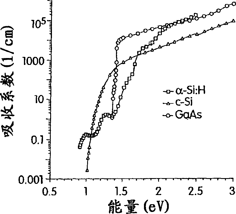
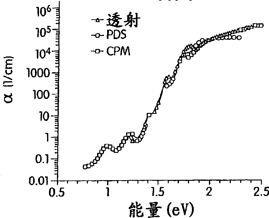
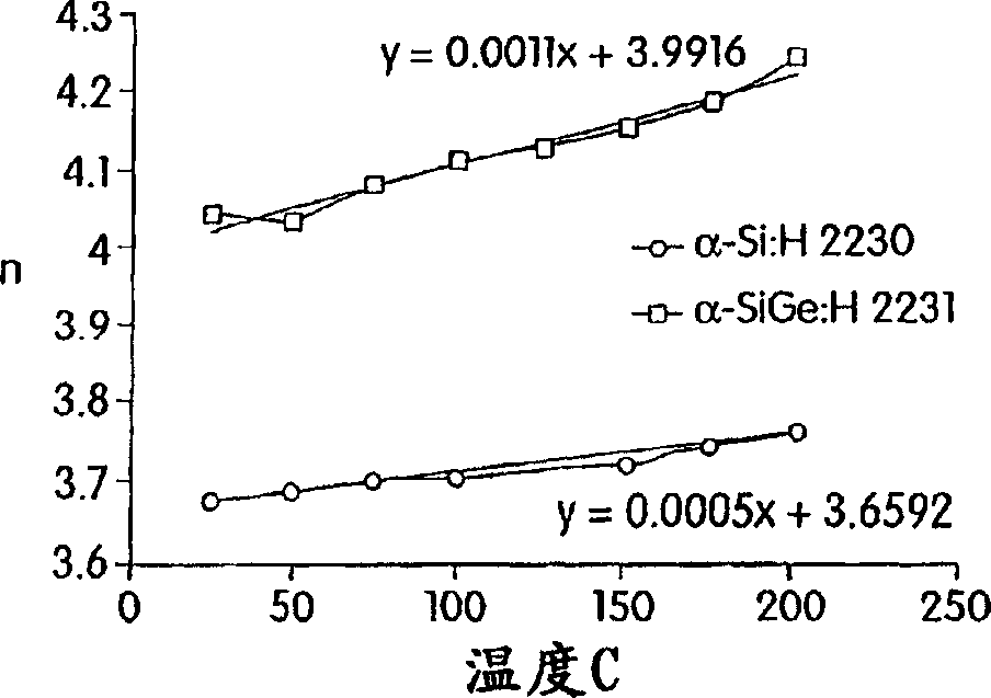
[0067] We have chosen to maximize, rather than minimize, the thermo-optic properties of a particular layer in a TFIC by exploiting the semiconductor thin film in the layer. These layers can be deposited by PECVD or CVD or other variants of PVD. Hydrogen-infused thermo-optic semiconductors such as α-Si:H or alloys for lower optical losses are used as high-refractive index layers (n=3.66 at 1500nm) and deposited by methods that have been optimized for the main optical communication wavelengths near 1500nm highly transparent (extinction coefficient k = 10 -6 ). Refractive index modulations [Delta]n / n of up to 4% can then be brought about by temperature changes over the range 25-45[deg.]C. These large temperature variations are best caused by an optically transparent conductive heating film such as n-type polysilicon adjacent to or alternating with other optical lay...


PUM

PropertyMeasurementUnit
thicknessaaaaaaaaaa
refractive indexaaaaaaaaaa

Abstract

According to various embodiments and aspects of present invention, there is provided a dynamically tunable thin film interference coating including one or more layers with thermo-optically tunable refractive index. Tunable layers within thin film interference coatings enable a new family of thin film active devices for the filtering, control, modulation of light. Active thin film structures can be used directly or integrated into a variety of photonic subsystems to make tunable lasers, tunable add-drop filters for fiber optic telecommunications, tunable polarizers, tunable dispersion compensation filters, and many other devices.

Description

Background technique [0001] The following background section discusses three general technical areas, including thin-film interference coatings, thin-film optical filters, and thermo-optic properties of semiconductors and their applications in photonic devices. [0002] thin film interference coating [0003] Thin film interference coatings represent one of the most mature and widely used aspects of optical technology. In general, TFIC relies on the sequential deposition of one or more layers (up to hundreds) of thin films with varying refractive index and other properties to achieve ideal spectral reflection and transmission, phase shift, or polarization over specified spectral bands. characteristic. For example, antireflective coatings have been used on lenses for almost a century. Other applications of TFIC include narrow bandpass filters, polarizers, color filters, and others. It is known in the art that an extremely wide range of optical properties can be engineered i...

Claims


Application Information

Patent Timeline
Patent Type & Authority Applications(China)
IPC IPC(8): G02B6/34G02B6/42G02F1/01G02F1/21
CPCY10T428/12729G02B6/4204G02B6/29395G02B6/4214G02F1/218G02B6/4224G02F1/0147Y10T428/12674G02F2203/055G02B6/4249G02B6/29398G02B6/4206G02F2203/48G02F2001/213G02B6/29358G02B6/4225G02B6/4215G02B6/4259G02B6/4266G02F1/213
Inventor 劳伦斯·多麦施尤金·马罗伯特·穆拉诺尼库雷·尼穆楚克亚当·佩恩史蒂文·谢尔曼马逖尔斯·瓦格纳吴明
Owner AEGIS SEMICON
Why Eureka
Try Eureka