Torque control device and torque control method

A technology of torque control and rotating shaft, which is applied in the direction of torque ripple control, speed control, DC motor speed/torque control, etc. It can solve the problem of low setting primary current value, inability to fully control torque, and inability to fully control the torque. Torque control and other issues to achieve the effect of suppressing vibration and noise and ensuring the low-speed rotation area

Inactive Publication Date: 2004-08-04
SANYO ELECTRIC CO LTD +1
View PDF1 Cites 13 Cited by
  • Summary
  • Abstract
  • Description
  • Claims
  • Application Information

AI Technical Summary

Problems solved by technology

[0006] Therefore, even when the load on the compressor is small, control is performed in consideration of the maximum load, and from the viewpoint of the secondary current value, even if there is a margin, the primary current value is set low. , resulting in the pr

Method used


Image

  • Torque control device and torque control method
  • Torque control device and torque control method
  • Torque control device and torque control method

Examples


Embodiment 1

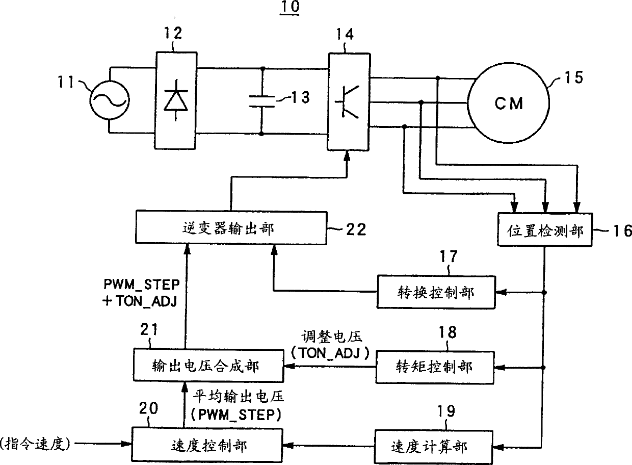
[0032] A preferred embodiment of the present invention will be described below with reference to the accompanying drawings. FIG. 1 is a block diagram showing a schematic configuration of an air conditioner according to an embodiment of the present invention.

[0033] In FIG. 1, if roughly distinguished, the air conditioner 10 includes: an AC power supply 11, a rectifier circuit 12, a power supply stabilization unit 13, a drive circuit 14, a compressor motor 15, a position detection unit 16, a conversion control unit 17, and a torque control unit. part 18, speed calculation part 19, speed control part 20, output voltage synthesis part 21, inverter output part 22.

[0034] The AC power supply 11 outputs the AC power to the rectification circuit 12 in order to supply the AC power for driving the entire air conditioner.

[0035] The rectification circuit 12 rectifies the AC power supplied from the AC power supply 11 , converts it into DC power, and supplies it to the power supply ...


PUM


Abstract

To suppress vibration and noises generated in a low speed rotation zone and secure a wide low speed rotation zone by performing optimum torque control even under a condition that a load of a compressor is low. A speed control part 20, an inverter output part 22 and a drive circuit 14 controls drive voltage applied to a motor driving a compressor. In parallel, a position detection part 16 and a torque control part 18 estimate a load of the compressor. The torque control part 18 and an output voltage synthesis part 21 regulates drive voltage based on the estimated load and controls fluctuation of rotary acceleration of a rotary mechanism of the compressor.

Description

technical field [0001] The present invention relates to a torque control device and a torque control method, and more particularly to a torque control technique for efficiently driving a motor driving a compressor at a low load. Background technique [0002] In conventional air conditioners, there is known a compressor driving device in which a brushless DC motor drives the rotor of the compressor. That is, when the torque changes like a ripple, the compressor itself may vibrate and generate noise. [0003] In order to solve the above-mentioned problems, in the technology described in Patent Document 1, the operation frequency of the compressor and the current value (primary current value) of the drive current supplied to the brushless DC motor are used to control the operation of the compressor. Torque control. [0004] [Patent Document 1] JP-A-2001-119981 [0005] Therefore, in actual control, considering the durability of the machine (the life of the motor parts), the ...

Claims


Application Information

Patent Timeline
IPC IPC(8): F04B49/06F04B49/00F24F11/02F24F11/46F24F11/49F24F11/64F24F11/86F24F11/89F25B1/00H02P6/06H02P6/08H02P6/10H02P6/16H02P6/17
CPCY02B30/741F25B2600/021Y02B30/70F04B35/04F04B49/06F04B49/20F04B2207/01F05B2270/1012F05B2270/20F05B2270/30F05B2270/602F24F1/08
Inventor 范合円福岛纪雄铃木健太郎日比秀二中岛利光
Owner SANYO ELECTRIC CO LTD
Why Eureka
Try Eureka