Lighting optical system and projection display device
An illumination optical system and optical resonance technology, applied in optics, using projection device, image reproducer, projection device, etc., can solve the problems of complex structure of display device, difficulty in cheap manufacturing of display device, and decrease in brightness of projected image
- Summary
- Abstract
- Description
- Claims
- Application Information
AI Technical Summary
Problems solved by technology
Method used
Image

Examples
Embodiment 1
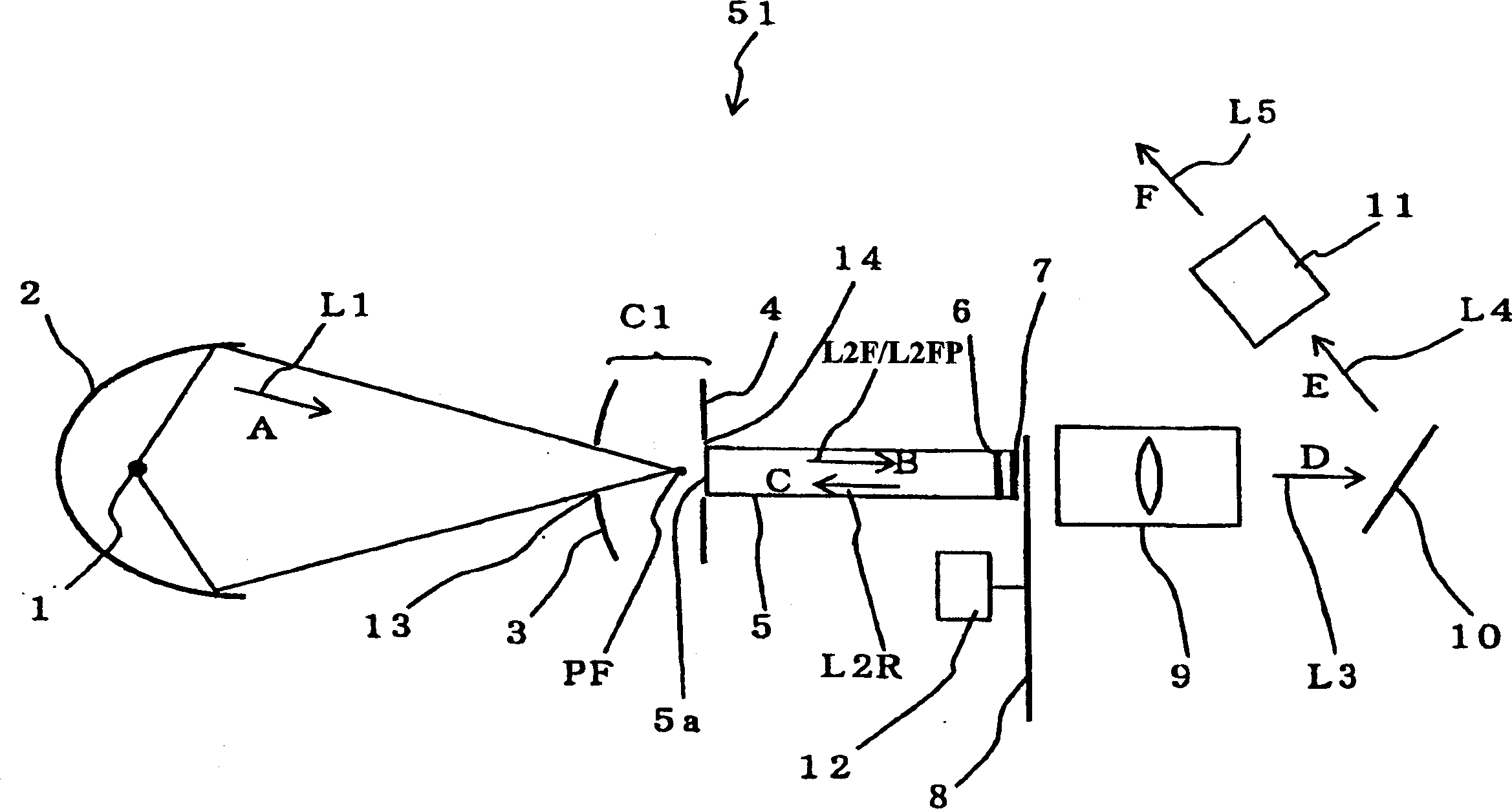
[0041] figure 1 It is a configuration diagram showing the configuration of the illumination optical system 51 according to Embodiment 1 of the present invention.
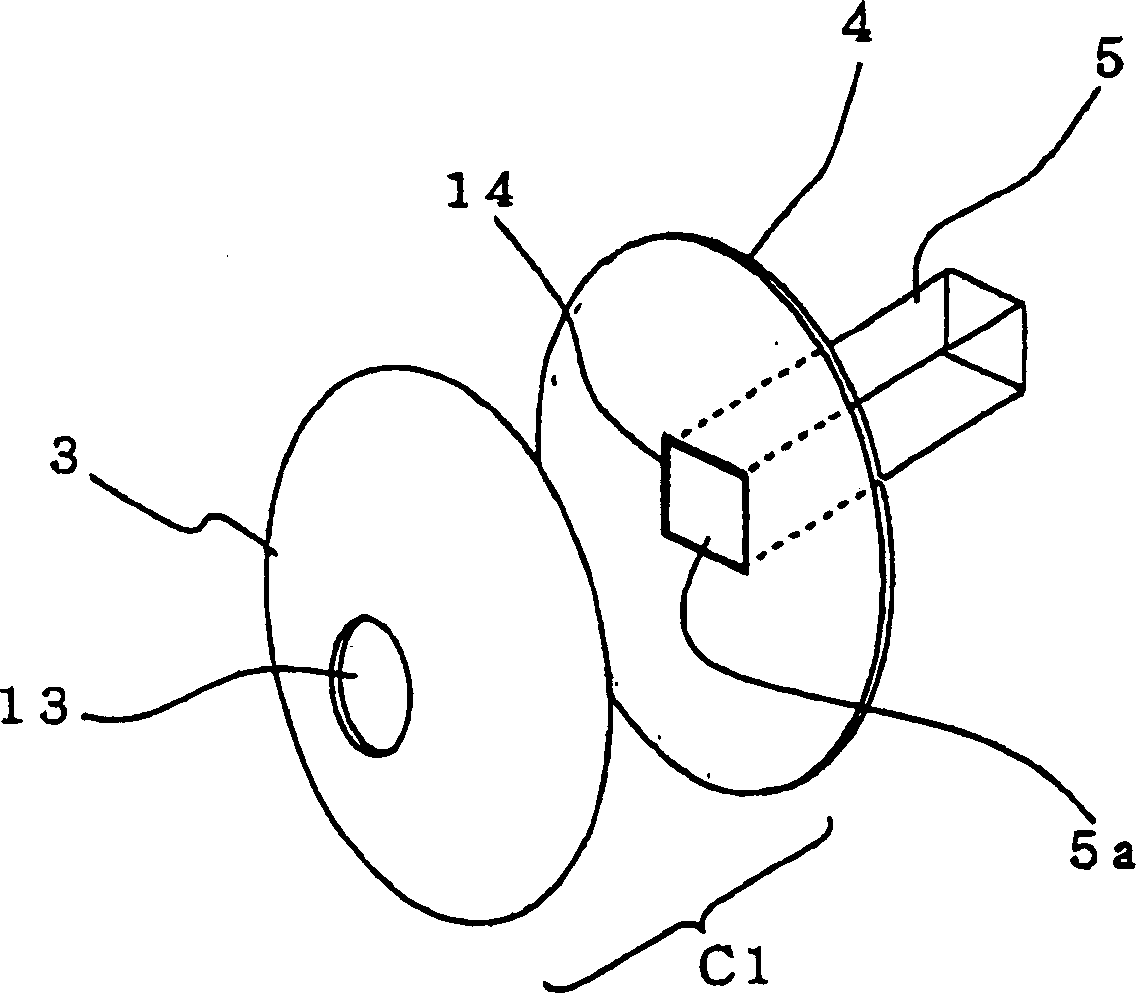
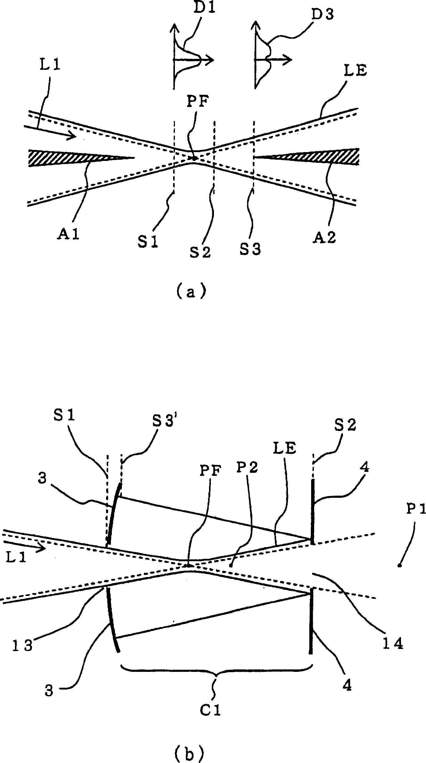
[0042] exist figure 1 In the illumination optical system 51 of , the lamp portion reflector 2 as a light collecting device is disposed near the lamp 1 as a light source. On the optical path of the light reflected by the lamp reflector 2, the second reflector 3, the first reflector 4, the columnar optical element 5, the 1 / 4 wavelength plate 6 as a phase plate, the reflector Type polarized light separator 7, color wheel 8, optical relay (relay) device 9, light valve 10 and projection lens 11.
[0043] Arrow A represents the direction of travel of light L1 reflected by lamp reflector 2, arrow B represents the direction of travel of light L2F inside cylindrical optical element 5, and arrow C represents the direction in which light L2F travels in the direction opposite to light L2F inside cylindrical optical element ...
Embodiment 2
[0085] Figure 6 is a diagram showing the configuration of the illumination optical system 52 according to Embodiment 2 of the present invention.
[0086] The difference between the illumination optical system 52 of the present embodiment 2 and the illumination optical system 51 of the above-mentioned embodiment 1 is that the columnar optical element 5 ( figure 1 ), and the 1 / 4 wavelength plate 6 and the reflective polarized light separation element 7 are replaced by the 1 / 4 wavelength plate 62 and the reflective polarized light separation element 72. Therefore, the common parts of the illumination optical system 52 of the second embodiment and the illumination optical system 51 of the first embodiment are given the same reference numerals, or the drawings and explanations are omitted, and the different features are mainly explained.
[0087] Such as Figure 6 As shown, by setting the 1 / 4 wavelength plate 62 and the reflective polarized light separation element 72 as the ob...
Embodiment 3
[0093] Figure 7 It is a configuration diagram showing the configuration of an illumination optical system 53 according to Embodiment 3 of the present invention.
[0094] exist Figure 7 In the illumination optical system 53, the lamp part reflector 2 is arranged near the lamp 1 as a light source. On the optical path of the light reflected by the reflector 2 of the lamp part, a lens 15, a polarized light converter 16, a second reflector 32, and a reflective polarized light splitter as a reflective polarized light splitter are sequentially arranged from the place close to the lamp 1. Device 17 , first mirror 42 , color wheel 82 , reflective liquid crystal light valve 102 , polarizer 18 and projection lens 112 .
[0095] First, the overall operation of the above-mentioned structure will be described below.
[0096] Arrow A indicates the advancing direction of the light L1 reflected by the lamp unit reflector 2 . The lens 15 inputs the light L1 and then outputs it to the pola...
PUM
 Abstract
Description
Claims
Application Information
 - R&D
- Intellectual Property
- Life Sciences
- Materials
- Tech Scout
- Unparalleled Data Quality
- Higher Quality Content
- 60% Fewer Hallucinations
Browse by: Latest US Patents, China's latest patents, Technical Efficacy Thesaurus, Application Domain, Technology Topic, Popular Technical Reports.
© 2025 PatSnap. All rights reserved.Legal|Privacy policy|Modern Slavery Act Transparency Statement|Sitemap|About US| Contact US: help@patsnap.com