Cootrol method for temperature system with big lag

A technology of hysteresis temperature and control method, applied in the direction of temperature control, temperature control using electric method, non-electric variable control, etc., can solve the problem of complex dynamic parameter expression, achieve clear physical meaning, reduce mechanical wear and prolong service time Effect

Inactive Publication Date: 2004-08-04
天津市易卡捷电子有限公司
View PDF4 Cites 8 Cited by
  • Summary
  • Abstract
  • Description
  • Claims
  • Application Information

AI Technical Summary

Problems solved by technology

For more complex systems, it needs to be expressed by second-order or even higher-order diff

Method used


Image

  • Cootrol method for temperature system with big lag
  • Cootrol method for temperature system with big lag
  • Cootrol method for temperature system with big lag

Examples


Embodiment Construction

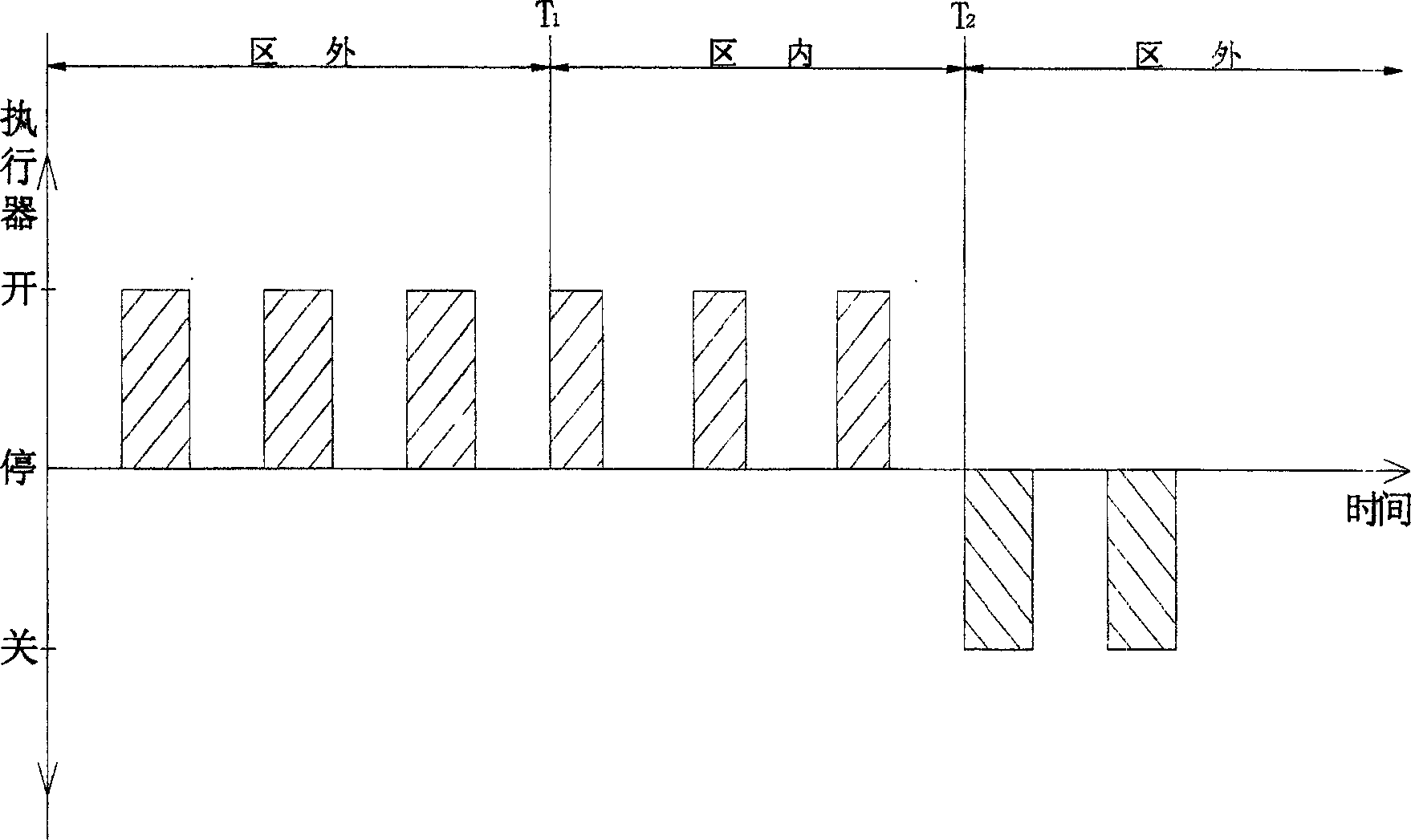
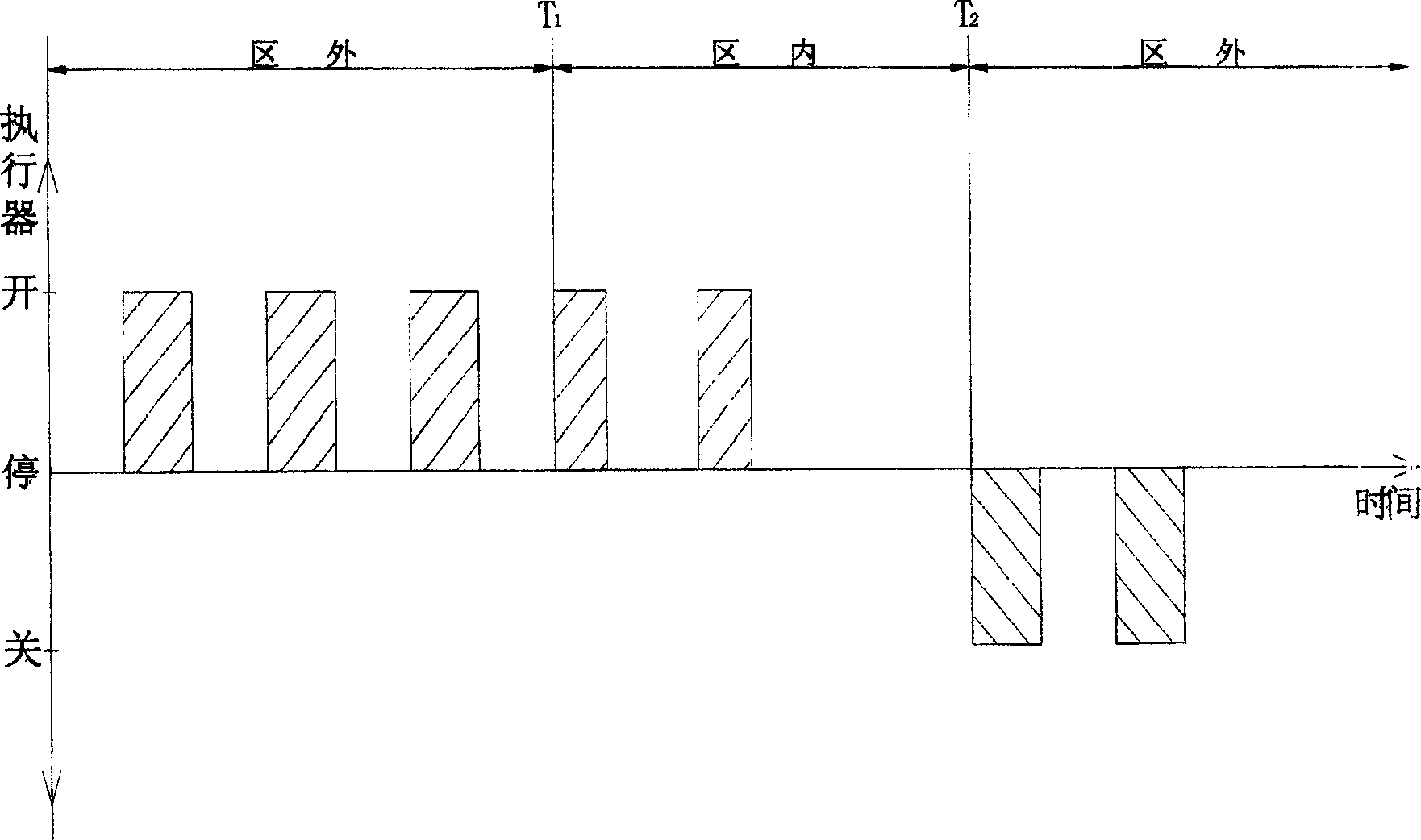
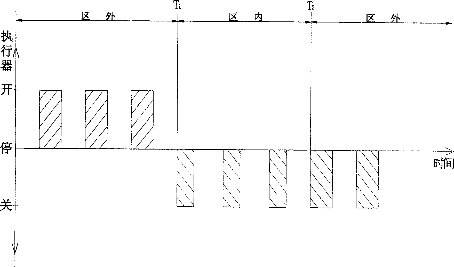
[0020] The control method of the larger hysteresis temperature system disclosed by the present invention can be implemented on the oil field heating furnace (6) by the following temperature control device: the device consists of a burner (5), a controller (1), a temperature sensor (2) , actuator (4), safety valve (3), ignition valve (7), igniter (8), as attached Figure 5 shown. Wherein the fuel of the burner (5) should be gas or liquid, and the burner (5) can be the gas burner described in Chinese patent application 02294106.1 or other gas or oil burners that can realize the combustion function. The controller (1) is a microprocessor-based device with a specific program. The temperature sensor (3) is a temperature switch, which can be a temperature relay, or a relay switch signal converted by a thermocouple, a thermal resistance and other temperature measuring elements through a secondary instrument. The actuator (4) is a motor-driven valve, such as an electric disc valve, ...


PUM


Abstract

A control method for the temp system with big lag is disclosed. As its input signal and output signal are switch values and its controlled output signal varies with the state of input temp signal and the regulation times, its control effect is very ideal. Its apparatus is composed of burner, controller, temp sensor and executor. It is suitable for the control to heating furnace of oil field.

Description

Technical field: [0001] The invention relates to a temperature system control method, especially a control method for a temperature system with a relatively large hysteresis. Background technique: [0002] In the process of industrial production and other occasions, the temperature control system is one of the most important control systems. However, among the main industrial control parameters including temperature, pressure, flow, and material level, temperature is the most difficult parameter to control, mainly due to the hysteresis (or inertia) of this type of system. We can analyze it through the most common gas or oil heating furnace in the oil field: the gas or oil burns through the burner to release heat, and the heat is transferred to the medium water to be heated through each heating surface in the furnace. The heat transfer process has both flame and The heat radiation of the high-temperature flue gas also has heat conduction and heat convection inside and outsid...

Claims


Application Information

Patent Timeline
IPC IPC(8): G05D23/00G05D23/19
Inventor 杨凝
Owner 天津市易卡捷电子有限公司
Why Eureka
Try Eureka