
Press fitting type spring connector

A connector and push-type technology, applied in the direction of clamping/spring connection, connection, fixed connection, etc., can solve problems that may not ensure stable electrical characteristics

Inactive Publication Date: 2004-08-18
ITO SEISAKUSHO KK
View PDF3 Cites 12 Cited by
  • Summary
  • Abstract
  • Description
  • Claims
  • Application Information

AI Technical Summary

Problems solved by technology

[0006] Similarly, in the "contact connecting device" of prior art 2 and the "connector for electrical connection" of prior art 3, when the electrical connection terminal of the electronic instrument is brought into contact with the front end of the contact pin, there is a problem that the contact pin is inclined. It is not always possible to ensure stable electrical characteristics

Method used


Image

  • Press fitting type spring connector
  • Press fitting type spring connector
  • Press fitting type spring connector

Examples


Embodiment Construction

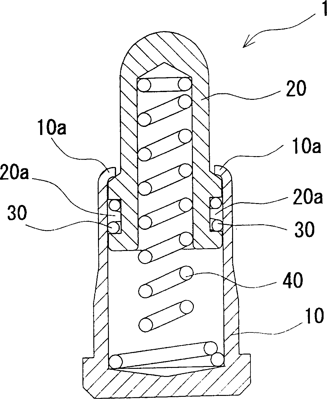
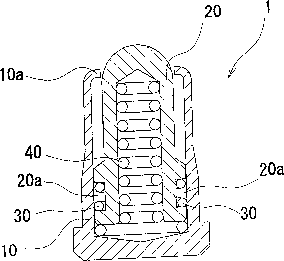
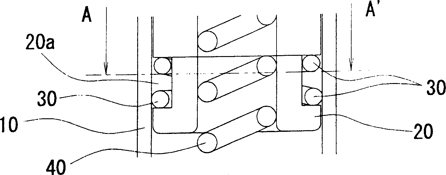
[0015] A push-type spring connector 1 according to an embodiment of the present invention is composed of a barrel 10 , a contact pin 20 , a contact ring 30 , and a coil spring 40 .

[0016] Such as figure 1 and figure 2 As shown, the cartridge 10 is constituted by a cylindrical body, and a space is provided inside. One end is designed as an opening, and the edge of the opening is provided with a pin-limiting portion 10a that shrinks toward the inside. The other end is made into a plane perpendicular to the axis of the cylinder 10 by deforming the edge. Inside the barrel 10 is provided a contact pin 20 .

[0017] One end of the barrel 10 of this embodiment is closed, and it can also be open at both ends, and the opening is closed with a cover at one end.

[0018] Such as figure 1 and figure 2 As shown, the stylus 20 is formed of a cylindrical body, and a space is provided inside. The front end is made into a hemispherical shape, and the diameter is smaller than the bot...


PUM


Abstract

With the press fitting type spring connector of the present invention, a contact pin 20 having a space inside is housed inside a space of a tube 10 in a slidable manner, along the axial center of the tube 10. A spring shaped touch ring 30 is mounted on an outer surface of the contact pin 20. Of two coils of the touch ring 30, the second coil has a larger diameter than the first coil, the first coil is always in contact with the contact pin 20, and the second coil is always in contact with the tube 10. A coil spring 40 has a tip housed inside the space of the contact pin 20, and a base section housed inside the tube 10. Accordingly, with the press fitting type spring connector of the present invention, housing the contact pin 20 inside the tube 10 along the axial center of the tube 10 makes it possible to always obtain stable electrical characteristics because of the touch ring 30 provided on the outer surface of the contact pin 20, and enables miniaturization.

Description

[technical field] [0001] The invention relates to a push-type spring connector, which is used in the detachable electrical connection parts of various electronic instruments. [Background technique] [0002] Present push-type spring connectors such as Japanese Patent Application Laid-Open No. 2002-56914 (Prior Art 1) claim 1 and figure 2 As shown, when the lead terminal slides, press the lead terminal until the inclined lead terminal penetration part of the lead terminal contacts the inner surface to prevent poor contact, and at the same time remove foreign matter mixed into the contact part of the lead terminal and the inner surface of the cylinder to prevent structural parts from burning. damage. [0003] In addition, claim 1 and figure 1 As shown, it uses the inclined surface at the rear end of the stylus provided to tilt the stylus and press the inner surface of the contact cylinder. [0004] Then there is the patent application No. 2000-251995 (prior art 3) claim 1 a...

Claims


Application Information

Patent Timeline
IPC IPC(8): G01R1/067H01R12/57H01R13/187H01R13/24
CPCH01R13/2421H01R13/187
Inventor 松井信久津川巧
Owner ITO SEISAKUSHO KK
Learn More