CT detector with integral air gap

A detector and air gap technology, applied in the field of CT detectors, can solve problems such as scintillator photodiode array rupture or disconnection, CT detector failure, CT system shutdown, etc.

Inactive Publication Date: 2004-09-08
GE MEDICAL SYST GLOBAL TECH CO LLC
View PDF0 Cites 8 Cited by
  • Summary
  • Abstract
  • Description
  • Claims
  • Application Information

AI Technical Summary

Problems solved by technology

Despite these advances, known optocouplers are still prone to cracking or disconnection of the scintillator and / or photodiode array
This premature rupture or disconnection can lead to catastrophic failure of the CT detector, thereby resulting in an entire detector replacement under warranty and the CT system having to be shut down

Method used


Image

  • CT detector with integral air gap
  • CT detector with integral air gap
  • CT detector with integral air gap

Examples


Embodiment Construction

[0024] The operating environment of the present invention is described below with respect to a four-slice computed tomography (CT) system. However, those skilled in the art will appreciate that the present invention is equally applicable to single-fault or other multi-fault structures. Furthermore, the invention will be described with respect to the detection and conversion of X-rays. However, those skilled in the art will further understand that the present invention can also be applied to the detection and transformation of other high-frequency electromagnetic energy. The invention will be described with respect to third generation CT scanners, but it is equally applicable to other CT systems.

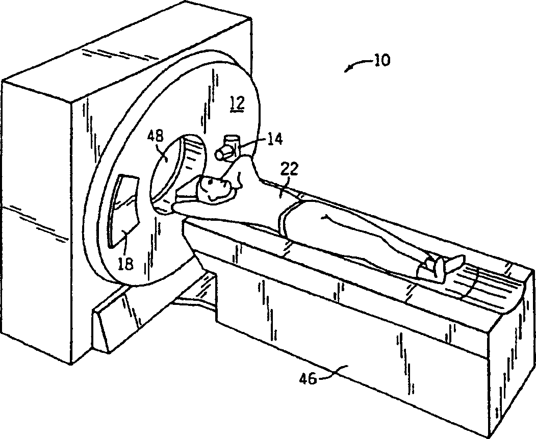
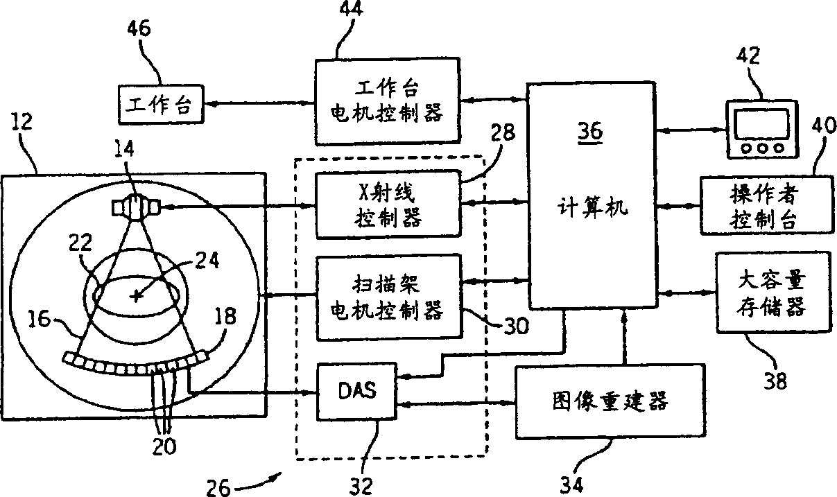
[0025] refer to figure 1 with 2 , shows a computed tomography (CT) imaging system 10 including a gantry 12 representing a third generation CT scanner. The gantry 12 has an X-ray source 14 that projects an X-ray beam 16 towards a detector array 18 on an opposite side of the gantry...


PUM


Abstract

The present invention is directed to an improved CT detector scintillator to photodiode optical coupling. The CT detector utilizes a controlled air gap between the photodiode array and the scintillator array together with an anti-reflective layer on the scintillator array. To improve the absorption of light at the photodiode array, the photodiode array includes a textured light reception surface. By incorporating a textured layer with the photodiode array, the light collection efficiency of the photodiodes is improved. The textured layer may extend along an x- and / or z-axis and the texturing may be in different forms. For example, the textured layer may include a series of pyramidally-shaped protrusions.

Description

technical field [0001] The present invention relates generally to diagnostic imaging, and more particularly to a CT detector with an integral air gap. More specifically, the CT detector includes a scintillator array with an anti-reflective layer attached to a photodiode array with a textured surface such that the scintillator array and photodiode There is a controlled air gap between the arrays. Background technique [0002] Typically, in a computed tomography (CT) imaging system, an x-ray source emits a fan beam at an object or target, such as a Imaging something. The beam is incident on the radiation detector array after being attenuated by the object. The intensity of the attenuated beam radiation received at the detector array typically depends on the degree to which the x-ray beam is attenuated by the object. Each detector element of the detector array produces an independent electrical signal representative of the attenuated beam received by each detector element. ...

Claims


Application Information

Patent Timeline
Patent Type & Authority Applications(China)
IPC IPC(8): G01T1/20A61B6/03A61B6/08G01N23/00G01T1/29G21K1/12H04N5/32H05G1/64
CPCG01T1/2985G01T1/2002
Inventor 戴维·M·霍夫曼
Owner GE MEDICAL SYST GLOBAL TECH CO LLC
Why Eureka
Try Eureka