Automatic evaporator defrosting on-off control method

An evaporator and control system technology, applied in defrosting, instruments, refrigerators, etc., can solve the problems of air flow rate drop, can not reflect the overall change of frost layer thickness, surface heat transfer coefficient drop, etc., to achieve the effect of reducing accuracy requirements

Inactive Publication Date: 2004-09-08
XI AN JIAOTONG UNIV
View PDF0 Cites 24 Cited by
  • Summary
  • Abstract
  • Description
  • Claims
  • Application Information

AI Technical Summary

Problems solved by technology

The increase in the thickness of the frost layer reduces the flow rate of the air entering the evaporator, and the surface heat transfer coefficient on the air side of the evaporator decreases, resulting in the deterioration of the performance of the refrigerator
The existing automatic control method of defrosting start and stop time is based on the measurement of the thickness of the frost layer at a local location. When the thickness of the frost layer at this location reaches a specified value, the thermistor installed at this location senses the change in temperature and starts Or stop the defrosting system, but this method cannot measure the average thickness of the frost layer, so it cannot reflect the overall change of the frost layer thickness
Another existing method is to measure the pressure difference between the inlet and outlet of the evaporator. When the pressure difference reaches a specified value, the defrosting system is started or stopped. However, the direct factor affecting the heat transfer coefficient of the air side surface of the evaporator is Air flow rate and pressure difference change are only one of the factors that reflect the change of flow rate, so it is better to control the start and stop time of defrosting with the change of pressure difference than to control the start and stop time of defrost with the change of airflow speed

Method used


Image

  • Automatic evaporator defrosting on-off control method
  • Automatic evaporator defrosting on-off control method
  • Automatic evaporator defrosting on-off control method

Examples


Embodiment 1

[0036] Example 1: Double-door air-cooled refrigerator evaporator electric heating defrost

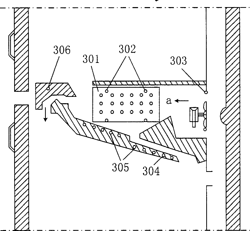
[0037] See image 3 , image 3 It is a schematic diagram of the internal distribution of some electric heating devices of a commonly used double-door air-cooled refrigerator. The figure includes: evaporator 301, evaporator defrost heater 302, fan blade hole heater 303, drain pipe heater 304, and Water tray heater 305, temperature-sensitive damper thermostat housing heater 306.

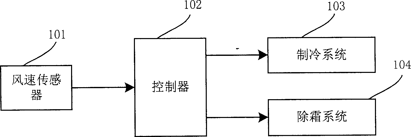
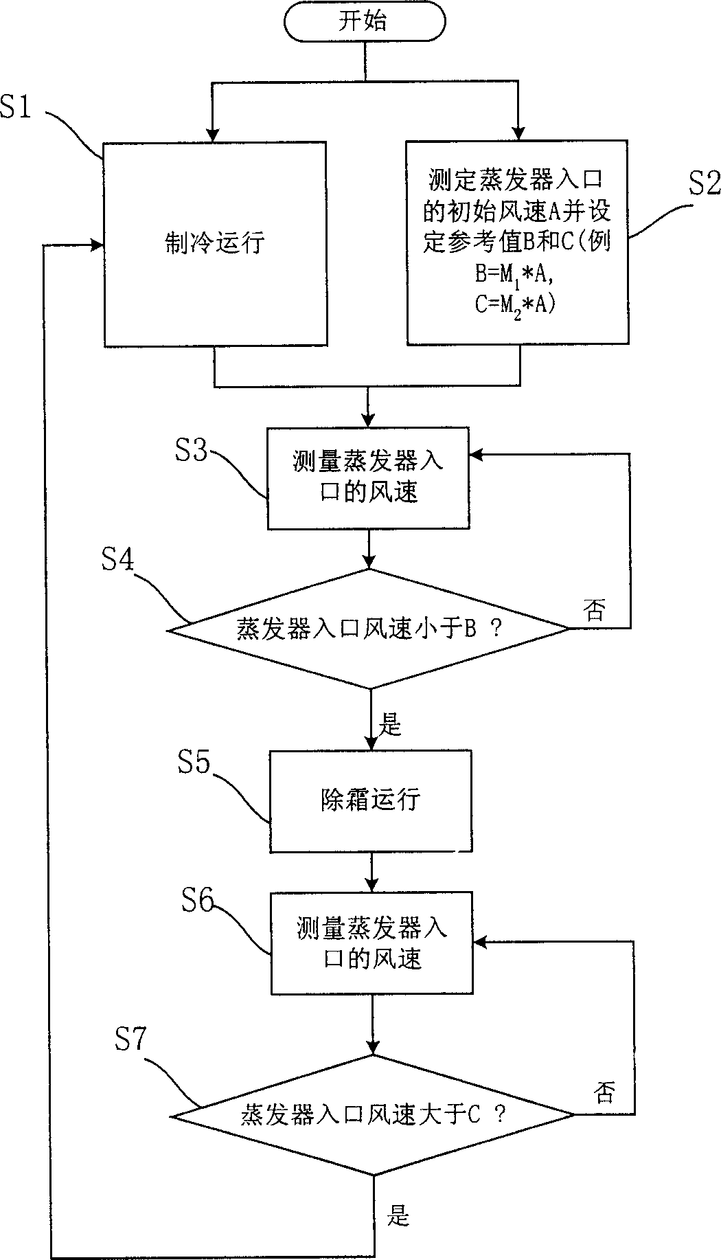
[0038] The evaporator 301 is located between the freezer compartment and the refrigerating compartment. Using the method of the present invention to automatically determine the defrosting start time, a wind speed sensor 101 is installed at the entrance position a of the evaporator 301. When the refrigerator is turned on and enters the cooling operation (step S1) The wind speed sensor 101 measures the initial wind speed A at the entrance of the evaporator, and sets reference values ​​B and C (step S2, B and C can be ...

Embodiment 2

[0039]Example 2: Air heat source heat pump evaporator (outdoor side heat exchanger) hot air flow defrosting

[0040] See Figure 4 , Figure 4 It is a schematic diagram of an air heat source heat pump type cooling and heating fan. The figure includes: evaporator (outdoor side heat exchanger) 401, outdoor side fan 402, compressor 403, indoor side fan 404, indoor side heat exchanger 405, fresh air outlet 406, Four-way valve 407.

[0041] Using the method of the present invention to automatically determine the start time of defrosting, a wind speed sensor 101 is installed at the inlet position a of the evaporator 401. When the air source heat pump unit is turned on and enters the cooling operation (step S1), the wind speed sensor 101 measures the initial inlet of the evaporator 401 Wind speed A, and set reference values ​​B and C (step S2, B and C can be set to 0.5 times and 0.9 times of A, respectively). During the subsequent cooling operation, the wind speed sensor 101 continuously...

Embodiment 3

[0042] Example 3: Defrosting of the hot air flow of the air cooler evaporator

[0043] See Figure 5 , Figure 5 It is a schematic diagram of the position of the air cooler evaporator. The figure includes: evaporator 501, liquid supply solenoid valve 502, return air solenoid valve 503, defrost solenoid valve 504, one-way valve 505, liquid supply pipe 506, air return pipe 507, defrost Hot air pipe 508, fan 509.

[0044] Using the method of the present invention to automatically determine the start time of defrosting, a wind speed sensor 101 is installed at the entrance position a of the evaporator 501. When the air cooler is turned on and enters cooling operation (step S1), the wind speed sensor 101 measures the initial wind speed A at the entrance of the evaporator 501 , And set reference values ​​B and C (step S2, B and C can be set to 0.55 times and 0.95 times of A, respectively). In the subsequent cooling operation, the wind speed sensor 101 continuously detects the wind speed at...


PUM


Abstract

The present invention is automatic evaporator defrosting on-off control method. The relative change in wind speed through the evaporator before and after the defrosting of the evaporator is used in controlling the start and the stop of defrosting. The method has the advantages of no need of measuring thickness of frost, no difficulty in measuring average thickness of frost layer, the reasonable determination of the defrosting on and off time based on only the air flow speed, and capacity of ensuring excellent heat transferring characteristic of the evaporator and the efficient operation of the refrigerating system.

Description

Technical field [0001] The invention belongs to refrigeration technology, and relates to a method for automatically controlling the start and stop timing of evaporator defrosting. This method is suitable for defrosting the evaporator in cold storage, heat pump and double-door air-cooled refrigerator. Background technique [0002] When the evaporation temperature is lower than 0°C, part of the water vapor in the air will freeze into frost on the surface of the evaporator. The increase in the thickness of the frost layer reduces the flow rate of the air entering the evaporator, and the surface heat transfer coefficient on the air side of the evaporator decreases, resulting in the deterioration of the refrigerator performance. The existing defrosting start and stop time automatic control method is based on measuring the thickness of the frost layer at a local position. When the thickness of the frost layer reaches a specified value, the thermistor installed at the position senses th...

Claims


Application Information

Patent Timeline
Patent Type & Authority Applications(China)
IPC IPC(8): F25B47/02F25B49/02F25D21/08F25D29/00G01F1/00
Inventor 周晋吴青平吴业正
Owner XI AN JIAOTONG UNIV
Why Eureka
Try Eureka