Mosaic array of ultrasound transducer by micromachining

An ultrasonic transducer and mosaic technology, applied in piezoelectric/electrostrictive transducers, fluids using vibration, ultrasonic/sonic/infrasonic diagnosis, etc., can solve the problem of expensive, complex dynamic focusing beams, and difficult to achieve portability And other issues

Inactive Publication Date: 2004-09-08
GENERAL ELECTRIC CO
View PDF2 Cites 16 Cited by
  • Summary
  • Abstract
  • Description
  • Claims
  • Application Information

AI Technical Summary

Problems solved by technology

Achieving dynamically focused beams in elevation and azimuth directions is very complex and expensive, especially for general imaging (vs. echocardiography) applications
Moreover, the size and power consumption of electronic components also make such systems difficult to implement portable

Method used


Image

  • Mosaic array of ultrasound transducer by micromachining
  • Mosaic array of ultrasound transducer by micromachining
  • Mosaic array of ultrasound transducer by micromachining

Examples


Embodiment Construction

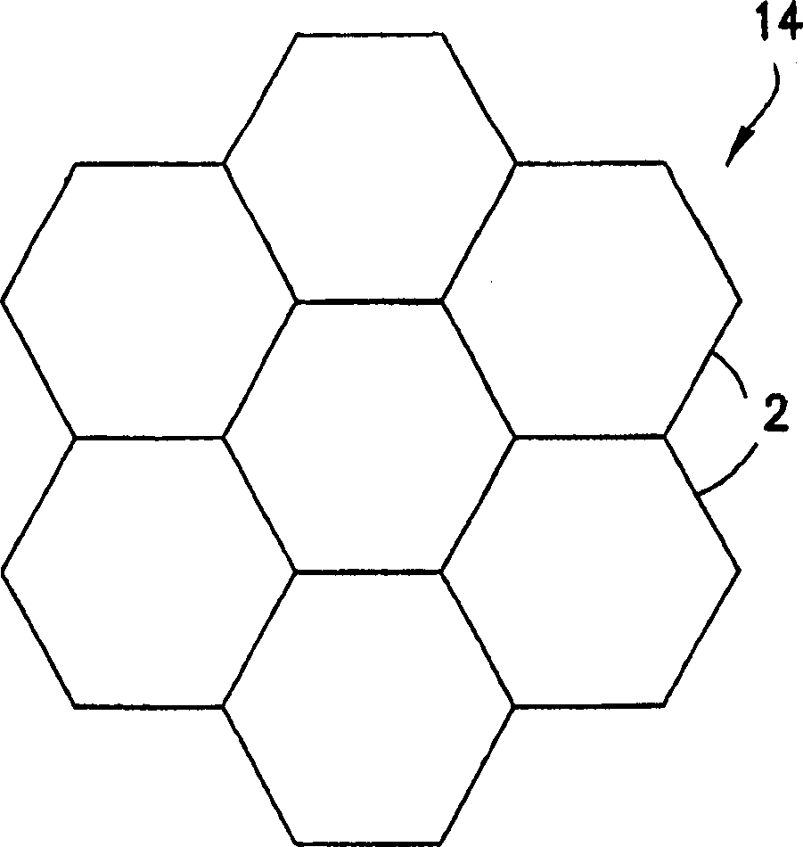
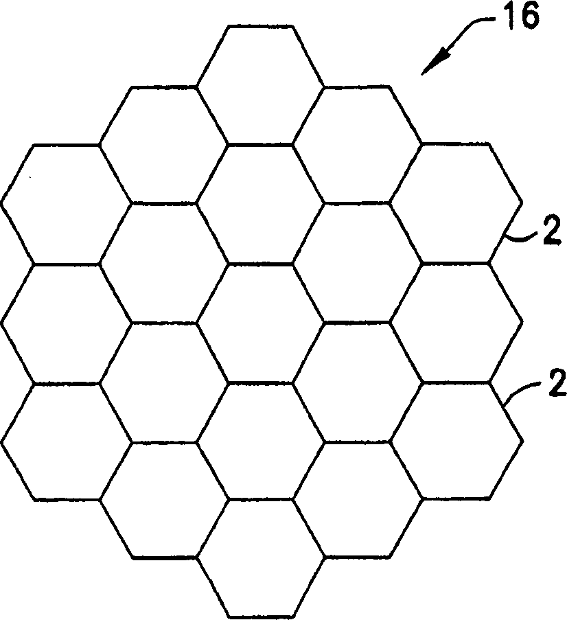
[0029] The present invention discloses a unique method of implementing a mosaic array using micromachined ultrasonic transducers (MUTs). For purposes of illustration, the present invention will be described using capacitive micromachined ultrasonic transducers (cMUTs). ), however, it needs to be understood that this disclosed aspect of the invention is not limited to the use of cMUTs, but can use pMUTs, or even diced piezoelectric ceramic arrays, where each diced subunit passes through an interconnect Connect to the switch layer below.

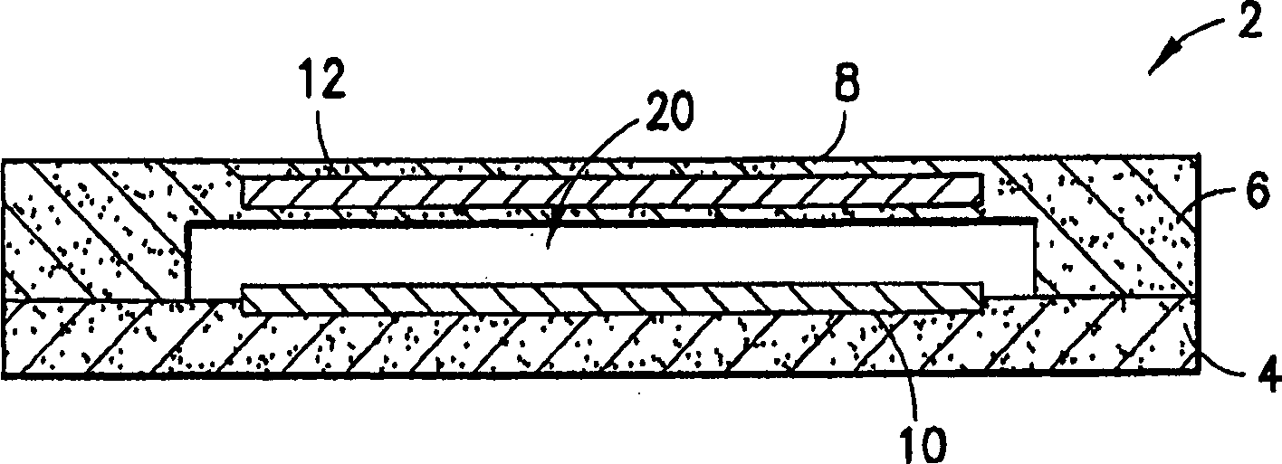
[0030] cMUTs are silicon-based devices that include small (eg, 50um) capacitive tympanic membrane patches or cells capable of transmitting and receiving ultrasonic energy, see figure 1 , figure 1A cross-section of a typical MUT transducer unit 2 is shown. An array of such MUT transducer elements is typically fabricated on a substrate 4, such as a silicon wafer. For each such MUT transducer unit, a thin film or diaphragm 8, which may be made...


PUM


Abstract

An ultrasound transducer array includes a multiplicity of subelements interconnected by a multiplicity of microelectronic switches, each subelement comprising a respective multiplicity of micromachined ultrasound transducer (MUT) cells. The MUT cells within a particular subelement are hard-wired together. The switches are used to configure the subelements to form multiple concentric annular elements. This design dramatically reduces complexity while enabling focusing in the elevation direction during ultrasonic image data acquisition.

Description

technical field [0001] The present invention relates generally to mosaic arrays of ultrasound transducer elements, and the use of micromachined ultrasound transducers (MUTs) in the arrays, one particular application of MUTs being ultrasound imaging systems for medical diagnostics . Background technique [0002] A traditional ultrasound imaging system consists of an array of ultrasound transducers that transmit an ultrasound beam and then receive the beam as it bounces off the object under study. This scan consists of a sequence of measurements in which focused ultrasound is transmitted, and after a short interval the system switches to receive mode, where the reflected ultrasound is received, beamformed, and displayed for processing. Typically, transmit and receive are focused in the same direction for each measurement to acquire data from a series of points along an acoustic beam or scan line. As reflected ultrasound is received, the ultrasound receiver is dynamically foc...

Claims


Application Information

Patent Timeline
Patent Type & Authority Applications(China)
IPC IPC(8): A61B8/00B06B1/02B06B1/06H04R17/00
CPCB06B1/0292E05B81/60E05B83/18E05B77/44E05Y2900/548
Inventor K·托梅纽斯R·A·菲舍尔D·M·米尔斯R·G·沃德尼基C·R·哈扎德L·S·史密斯
Owner GENERAL ELECTRIC CO
Why Eureka
Try Eureka