Short cirucit failure current limiter using solid state switch

A short-circuit fault, solid-state switching technology, applied in emergency protection circuit devices, circuit devices, emergency protection circuit devices for limiting overcurrent/overvoltage, etc., can solve problems such as high price, poor reliability, and large device loss

Inactive Publication Date: 2004-09-15
SOUTH CHINA UNIV OF TECH
View PDF0 Cites 9 Cited by
  • Summary
  • Abstract
  • Description
  • Claims
  • Application Information

AI Technical Summary

Problems solved by technology

[0004] 2. Superconducting current limiter
Due to the complex technology of the superconducting system, the rectifier element works under high voltage

Method used


Image

  • Short cirucit failure current limiter using solid state switch
  • Short cirucit failure current limiter using solid state switch
  • Short cirucit failure current limiter using solid state switch

Examples


Embodiment Construction

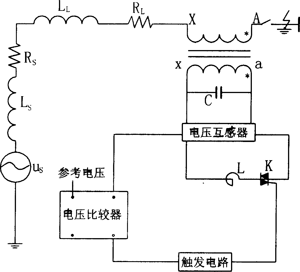
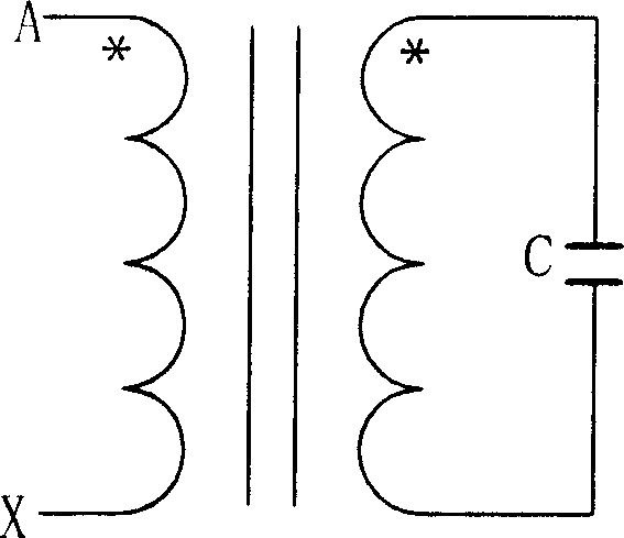
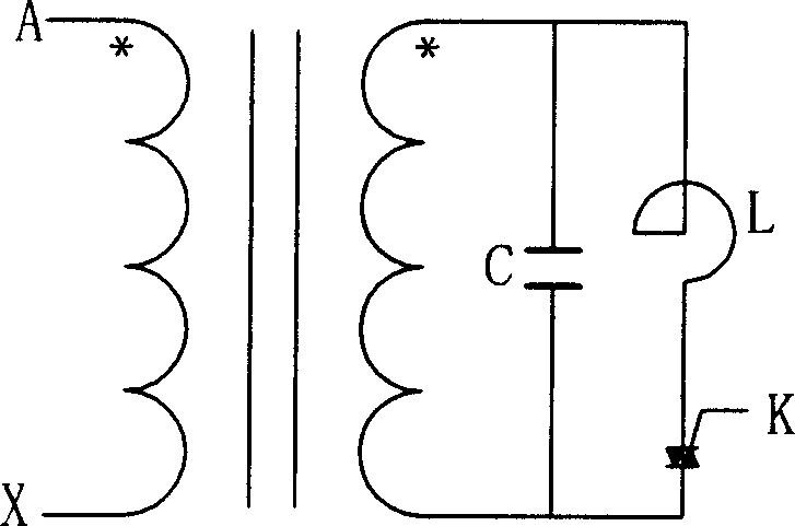
[0021] Such as Figure 1 to Figure 6 As shown, the present invention includes: a transformer with a suitable transformation ratio whose magnetic circuit is linear and whose iron core is in an unsaturated state during the normal operation of the power grid system and during the short-circuit fault time, and the primary side of the transformer is connected in series with the busbar of the power grid; Parallel resonant circuit, including a capacitor C with appropriate capacity, an inductor L with appropriate inductance, and a thyristor K, where the inductor L and the thyristor K are connected in parallel with the capacitor C, and both ends of the capacitor C are connected in parallel to the secondary of the transformer When designing the series transformer, capacitor and inductor of this embodiment, the transformer should first meet the following conditions: the transformer core is in an unsaturated state during the normal operation of the system and when a short-circuit fault occ...


PUM


Abstract

The current limiter comprises a transformer, a parallel-resonant circuit and voltage detection and trigger circuit. Primary side of the transformer is cascaded into busbar of power network. The parallel-resonant circuit includes capacitor C, inductance L and thyristor K; inductance L cascaded to thyristor K is connected to capacitor C in parallel; two ends of capacitor C are connected to secondary ends of transformer. The current limiter with the said structure makes peak of short circuit current in power network be clipped off, and plays good effect of restraining whole short circuit current so as the prevent electrical equipments from impulsion of large electrical current. Utilization of the current limiter will reduce breaking capacity of breaker accordingly, bringing economic benefit. Structure of the invention is simple. thyristor K is only needed to close, but not needed of turnning off. closing time is less than 200ms so as to raise service life and reliability of thyristor.

Description

technical field [0001] The invention relates to the field of power system automation and belongs to flexible AC power transmission technology, in particular to a short-circuit fault current limiter which uses a solid-state switch to control the short-circuit fault current and its rising rate of the power system. Background technique [0002] The development of power electronics technology has made flexible power transmission technology (FACTS) widely valued in the automatic control of power systems. In the past, system parameters (such as voltage, phase, impedance, etc.) control. In quite a lot of FACTS control devices, the core component is the adjustable reactor working under high voltage and high current conditions. For example, the power system fault current limiter is one of the FACTS control devices. To sum up, the fault current limiters currently being researched and tested can be divided into the following two categories: [0003] 1. A fault current limiter consis...

Claims


Application Information

Patent Timeline
IPC IPC(8): H02H9/02
Inventor 刘永强
Owner SOUTH CHINA UNIV OF TECH
Why Eureka
Try Eureka