Method and apparatus for leak-testing electroluminescent device

An electroluminescence device and photoluminescence technology are applied in the field of electroluminescence device and electroluminescence device inspection, which can solve the problems of short storage period of leaking devices, difficulty in quickly identifying leaks in devices by visual inspection, etc.

Inactive Publication Date: 2004-09-15
KONINKLIJKE PHILIPS ELECTRONICS NV
View PDF0 Cites 4 Cited by
  • Summary
  • Abstract
  • Description
  • Claims
  • Application Information

AI Technical Summary

Problems solved by technology

However, the use of getters is actually disadvantageous for manufacturers
It makes quick visual identification of device leaks difficult, as damage to the device in the form of dark spots in the luminescent substance is delayed
In fact, leaking devices have a very short shelf life and they should be thrown away before reaching the user

Method used


Image

  • Method and apparatus for leak-testing electroluminescent device
  • Method and apparatus for leak-testing electroluminescent device
  • Method and apparatus for leak-testing electroluminescent device

Examples


Embodiment Construction

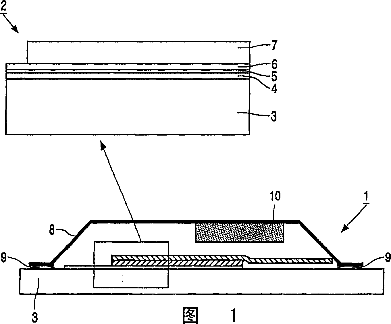
[0032] FIG. 1 schematically shows the main part of an electroluminescent device 1. As shown in FIG. The electroluminescent device 1 comprises a base layer 3 (of the order of 1 mm thick glass) carrying the EL element 2 . The EL element 2 is a laminate comprising an ITO (on the order of 150 mm thickness) conductive layer 4, a transparent PEDOT (on the order of 200 mm thickness) anode layer 5, an electroluminescent (organic on the order of 100 mm thickness) layer 6 and A (eg 5nmBA coated with 100nm Al) metal cathode layer 7. The EL element 2 is encapsulated between the glass substrate 3 and a separate metal cover 8 which is bonded to the glass substrate 3 by an epoxy edge seal 9 . A getter 10 (BaO and / or CaO) is placed inside the package to remove water penetrating through the epoxy edge seal 9 .

[0033] A particular embodiment of the invention is characterized in that the organic layer comprises an electroluminescent polymer. The electroluminescent polymer is a suitable EL m...


PUM


Abstract

A method of detecting the leak-in of oxygen in an organic electroluminescent device via the extent of photo-degradation of the electroluminescent organic material is described. The photo-degradation of the electroluminescent organic material is induced by the presence of oxygen, and can be detected by comparing the photo luminescence of the material, before and after illumination of the material with light (e.g. form a laser). Photo-degradation due to the presence of oxygen in an encapsulated organic electroluminescent device is evidence for a leak in the device, which leak will result in a shorter lifetime of the device. The invention provides a fast, non-destructive method of inspecting organic electroluminescent devices on leakage, immediately after their production. Leak devices can be identified and discarded, even on-line.

Description

technical field [0001] The invention relates to a leak detection method and instrument for an electroluminescent device having at least one organic light-emitting diode, said electroluminescent device being packaged in a casing. The invention also relates to electroluminescent devices which are suitable for inspection or have been inspected. [0002] Specifically, the present invention relates to the inspection of electroluminescent devices comprising: [0003] - an electroluminescent element comprising [0004] - an electroluminescent organic layer disposed between the hole injection electrode and the electron injection electrode; and [0005] - a casing, the casing includes [0006] - a first forming section, a second forming section and [0007] - an electrical connection of an electrode contacting the electroluminescent element; [0008] - said housing encloses said electroluminescent element, [0009] - said electroluminescent element is mounted on said first shaped...

Claims


Application Information

Patent Timeline
Patent Type & Authority Applications(China)
IPC IPC(8): H05B33/12G01R31/26H01L51/50H01L51/52H05B33/04
CPCH01L51/5237H10K50/846G01R31/26H01L22/00
Inventor A·J·G·曼克P·范德维耶
Owner KONINKLIJKE PHILIPS ELECTRONICS NV
Why Eureka
Try Eureka