Intelligent antenna up wave beam forming method and its device

A smart antenna and beamforming technology, applied in the directions of antennas, antenna arrays, selection devices, etc., can solve the problems of complex implementation of adaptive smart antennas, and achieve the effect of reducing the amount of calculation, combating channel changes, and suppressing the influence of interference.

Inactive Publication Date: 2004-09-29
ZTE CORP
View PDF1 Cites 14 Cited by
  • Summary
  • Abstract
  • Description
  • Claims
  • Application Information

AI Technical Summary

Problems solved by technology

[0009] The purpose of the present invention is to overcome the shortcomings of the pre-multi-beam smart antenna system, solve the complex pro...

Method used


Image

  • Intelligent antenna up wave beam forming method and its device
  • Intelligent antenna up wave beam forming method and its device
  • Intelligent antenna up wave beam forming method and its device

Examples


Embodiment Construction

[0040] The implementation of the technical solution will be further described in detail below in conjunction with the accompanying drawings. According to these flow charts and structural diagrams, those skilled in the same field can easily realize these modules.

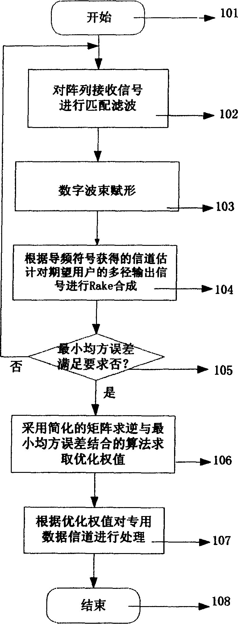
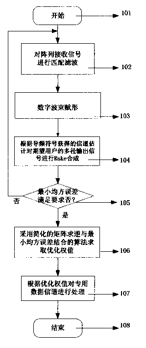
[0041] figure 1 It is a flow chart of the method of the present invention. In the adaptive smart antenna, the weights corresponding to the air domain or the air and time domain processing can be adjusted arbitrarily according to a certain adaptive algorithm to match the current transmission environment as much as possible, and the corresponding smart antenna receiving beam can be any pointing to. In practice, because the algorithm is often very complex, it is more difficult to realize. Therefore, the starting point of the present invention is to optimize the system structure and reduce the calculation amount of the algorithm. The method described in the present invention can be realized according to the following ...


PUM


Abstract

A method for forming an intelligent antenna up-line beam includes: matching and filtering the signals received by each element of the array antenna, to carry out digit beam shaping, proceeding in Rake synthesis to the multiroute output signals of desired users according to the estimation got from the pilot symbols, to evaluate an error signal and judge if the smallest square error is in the limit of the convergence threshold to evaluate an optimize weight value applying the algorithm of combining simplified matrix inversion and the smallest square error to process the special data channel information . The device includes an antenna formed by N antenna arrays, N RF channels, N matched filter modules, a beam form module, a channel estimation and compensation and a Rake merge module, a parameter module feed back estimation modules and a weight.

Description

technical field [0001] The invention relates to a receiving technology of an intelligent antenna in digital wireless communication, in particular to an uplink self-adaptive beam forming method and a device thereof for an intelligent antenna base station of a wideband code division multiple access (WCDMA) system. Background technique [0002] In the digital wireless communication system, due to the interference of various noises, multipath and fading in the space channel, the nature of the signal received by the receiver is not very ideal. In order to receive signals effectively, a variety of technologies are used in the receiver system to improve the receiving performance of the system, such as the RAKE combination technology in the CDMA system. The so-called Rake combination is to use a set of correlation receivers, one for each path, each correlation receiver is correlated with a delayed version of the same desired signal, and then the outputs of these correlation receiver...

Claims


Application Information

Patent Timeline
IPC IPC(8): H04B7/08H01Q21/00H04B1/707H04B7/26H04L25/02H04L25/03
Inventor 王衍文
Owner ZTE CORP
Why Eureka
Try Eureka