Variator air valve device for IC engine

An internal combustion engine, variable technology, applied in the direction of valve devices, non-mechanically actuated valves, mechanical equipment, etc., which can solve the problems of cost-increasing devices, increased power consumption, and insufficient fuel consumption.

Inactive Publication Date: 2004-10-06
NISSAN MOTOR CO LTD
View PDF1 Cites 1 Cited by
  • Summary
  • Abstract
  • Description
  • Claims
  • Application Information

AI Technical Summary

Problems solved by technology

In the case of low oil pressure (high oil temperature), in order to ensure the operational responsiveness of both variable valve mechanisms, the capacity and size of the oil pump are increased, resulting in an increase in cost and an increase in the size of the device.
Alternatively, when at least one of the variable valve mechanisms is electric, the cost increases and the power consumption increases, making it impossible to obtain sufficient fuel consumption as the original purpose of the variable valve mechanism. Improvement effect

Method used


Image

  • Variator air valve device for IC engine
  • Variator air valve device for IC engine
  • Variator air valve device for IC engine

Examples


Embodiment Construction

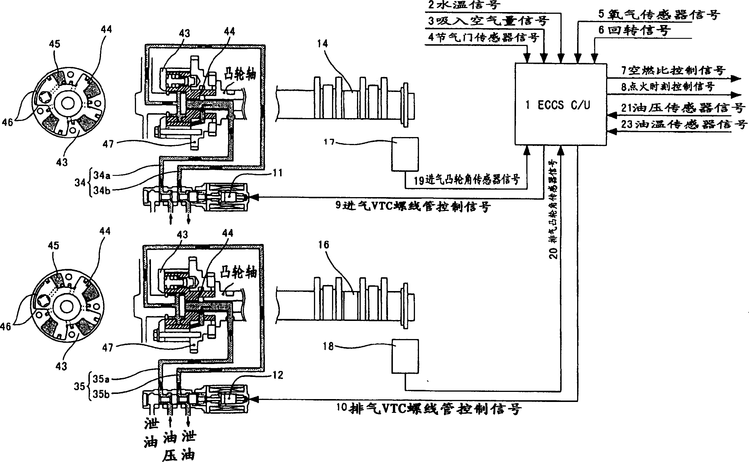
[0020] The preferred embodiments of the present invention will be described in detail below based on the drawings. in figure 1 Among them, the intake-side variable valve timing mechanism (hereinafter referred to as intake VTC) 13 as the intake-side variable valve mechanism can continuously change the valve timing of the intake valve as the exhaust side of the exhaust-side variable valve mechanism. The air-side variable valve timing mechanism (hereinafter referred to as exhaust VTC) 15 can continuously change the valve timing of the exhaust valve. These VTC (Valve Timing Controls) themselves are known technologies as disclosed in the above-mentioned Japanese Patent Application Laid-Open No. 2002-161721, and are briefly described here.

[0021] Each VTC has a housing 43 fixed to a cam sprocket 47 that rotates in conjunction with the crankshaft, and vanes 44 housed in the housing 43 and fixed to the intake camshaft 14 or the exhaust camshaft 16. Between the vane 44 and the casing 43...


PUM


Abstract

An inlet valve side and an exhaust valve side are respectively provided with a valve timing change mechanism (VTC) actuated by oil pressure from the oil pump for changing a valve lift characteristic. When an oil temperature Ot detected by an oil temperature sensor becomes higher than a predetermined second oil temperature threshold Ot2 (S15a), actuation of the exhaust VTC is prohibited (S16a). When the oil temperature Ot exceeds a first oil temperature threshold Ot1 which is higher than the Ot2, actuation of the inlet VTC is prohibited.

Description

Technical field [0001] The present invention relates to a variable valve device of an internal combustion engine in which a variable valve mechanism driven by hydraulic pressure is provided on both the intake side and the exhaust side. Background technique [0002] In order to increase the output of the internal combustion engine and improve the fuel consumption performance, various variable valve mechanisms that can change the valve lift characteristics of the intake and exhaust valves have been proposed in the past. For example, Patent Document 1 discloses a variable valve mechanism in which a hydraulic actuator and an electric actuator are used in combination. [0003] (Patent Document 1) [0004] Japanese Patent Publication No. 2002-161721 [0005] When a variable valve mechanism that is driven by hydraulic pressure from a hydraulic source such as an oil pump to change valve lift characteristics is provided on both the intake side and the exhaust side, there are the following...

Claims


Application Information

Patent Timeline
Patent Type & Authority Applications(China)
IPC IPC(8): F01L13/00F01L1/34F01L9/02F02D13/00F02D13/02
Inventor 鸟海真树新藤茂辉高木裕介
Owner NISSAN MOTOR CO LTD
Why Eureka
Try Eureka